Traffic Loader#
The SSD task Traffic Loader provides the calculation of result envelopes for traffic loads of road bridges.
The computation of the result envelopes (of internal forces, displacements and RSETs) is based on the evaluation of influence lines.
Lanes#
Define the lanes, where the traffic passes over the bridge. These lanes are used in the tab Load Groups to position load trains in the relevant constellations.
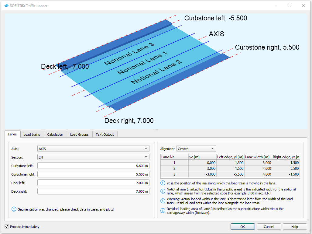
Axis - Choose a reference axis from those created with SOFiPlUS(-X) or SOFIMSHC. The positions of the curbstones and the egdes of the bridge deck are in reference to this axis.
Section - Specify the position of the lanes on the bridge deck and their width. By choosing a design code lanes will be automatically created based on the provisions of the code. Alternatively it is also possible to create user defined lanes.
Curbstone left/right - Specify the position of the curbstones.
Deck left/right - Specify the position of the edges of the bridge deck.
Alignment - Usually several sets of lanes are created in different alignments depending on the requested Section and the geometry of the bridge deck. Use this selection to visualize and check the created lanes for the different alignments and the lane IDs.
See also
For more information about lanes and the created lanes especially for the Eurocode (EN) setting see the following page Traffic Loader - Lanes.
Load Trains#
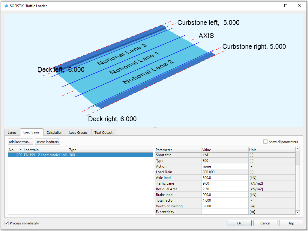
Define the load trains to be used in the calculation.
Calculation#
Select the options for the calculation of the results.
Select results#
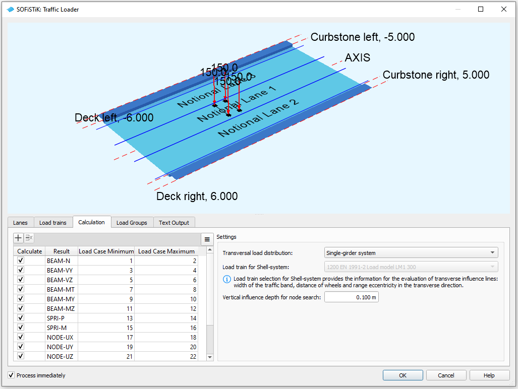
Add and select the results (internal forces, displacements, RSET-results) that should be evaluated.
For each result a number is specified for the Load Case Minimum and Load Case Maximum. The corresponding result envelopes are saved in a load case with a number that consists of the given number plus the Base LC number (see tab Load Groups).
Settings#
Transversal load distribution - There are several options available how the transversal load distribtion can be investigated:
For pure beam systems a distribution can be chosen based on knowledge about the system:
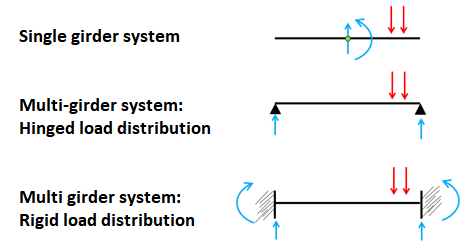
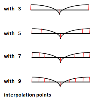
For shell (and hybrid) systems the investigation of the load distribution is based on transverse influence lines, that can be evaluated
Note
Generally the calculation is more exact with more interpolation points, however it will also take more time to run.
For the evaluation of the transverse influence lines for shell and hybrid systems the width and wheel spacing in cross direction of the load train is important. Therefore you have to specify also the load train which provides the necessary information in these cases.
Vertical influence depth for node search - This defines the vertical limits of the region for the node search below the lane. Note that nodes above the lane resp. reference axis are never considered.
Load Groups#
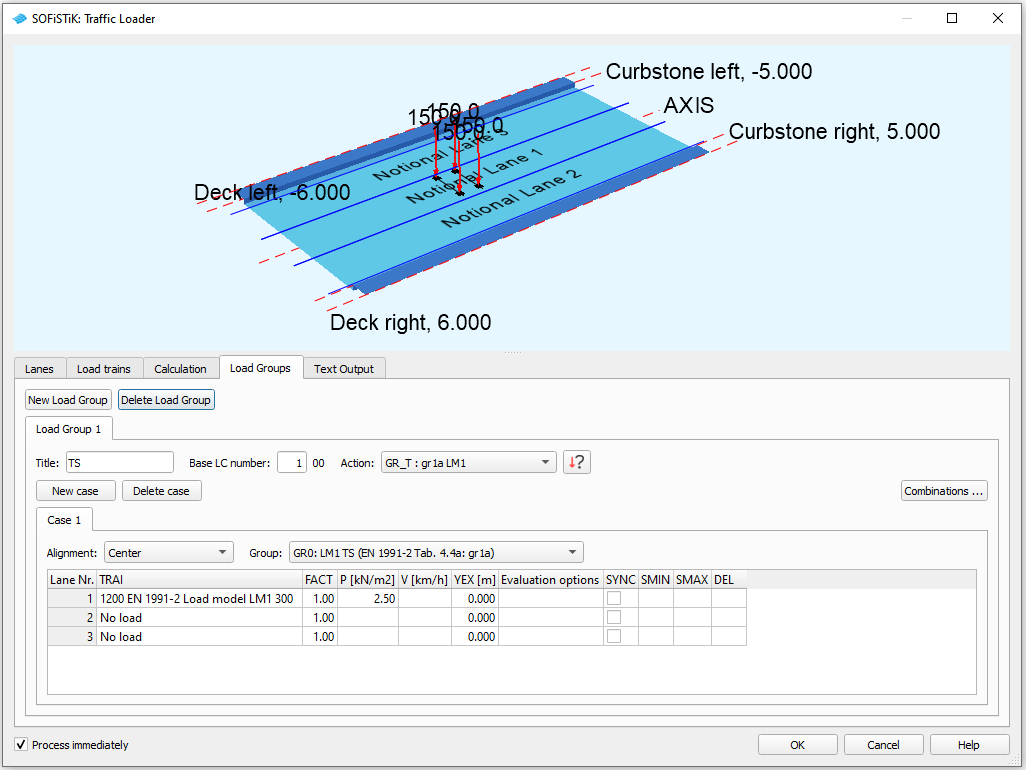
Define the load constellations for the calculation.
Load Group#
A load group is the set of load positions for which the result envelopes are created. Usually a load group comprises several Cases of load constellations for a certain load model or combinations of load models.
Title - Specify a title for the Load Group. This will be part of the title of the load cases that contain the result envelopes. This will help you to keep an overview over the created loadcases.
Base LC number - The result envelopes are saved in a load case with a number that consists of the Base LC number plus the number for the individual results (see tab Calculation).
Action - Specify the action for the created result envelopes. Note that the action has to be defined in the Action Manager before.
Note
Usually the result envelopes are used in the task CSM Bridge Design - Superpositioning or MAXIMA to create the final design envelopes. Therefore make sure that the assinged actions are correctly defined for the superpositioning.
Cases#
Each load group can have several Cases, where each Case defines a certain constellation of load trains in cross direction.
Alignment - Switch between the lane sets for the different alignments.
Group - Select certain parts of the load trains for the application.
TRAI - Select the load train to be applied in the lane.
FACT - Specify a multiplication factor for the loading.
P - Specify the loading on residual area. Per default this is taken from definition in the load train, but it can also be adjusted here.
V - Specify the velocity of the load train. Depending on the load train and design code this input can affect impact factors and centrifugal loads.
YEX - Specify a fixed excentricity of the load train within the lane (positive values for a shift to the right). Note that loads that are outside of the lane are not applied in the calculation.
Evaluation options - Set special options for the evaluation. For a description of these advanced settings see manual of module ELLA - command reference for POSL.
SYNC - Switch on the synchronization of load trains. Synchronized loads trains are applied at the same position in longitudinal direction.
SMIN, SMAX, DEL - In general the program automatically places the loading at the most unfavourable position in the lanes and no input is required. However for special cases the region for the search of the decisive load position can be limited via minimum (SMIN) and maximum (SMAX) station values on the reference axis. It is also possible to prescribe the density of the grid that is used for the initial search of the most unfavourable load position (see also manual of module ELLA, section 2.6.2). This can be used in the rare case that the algorithm has problems to find the correct load positions.
Note
By default the Cases are treated as mutually exclusive. This means that for each element a single Case provides the decisive extreme value for the investigated result envelope. However it is also possible to define Combinations of individual Cases.
Combinations#
Define combinations of cases that should act together.
Create a new combination by clicking on the corresponding button.
Click on a case and add it to the combination via the >> button.
Type - Specify how the combinations are treated in the superposition. Following options are available.
G - Combination is acting permanently (i.e. always applied).
Q - Combination is acting only if unfavourable.
A0-A9 - Among all Combinations that are assinged to the alternative group AX only the most unfavourable one is applied (i.e. the combinations belonging to AX are mutually exclusive).
Factor - Define a factor to be applied on the loads within the combination
Text Output#
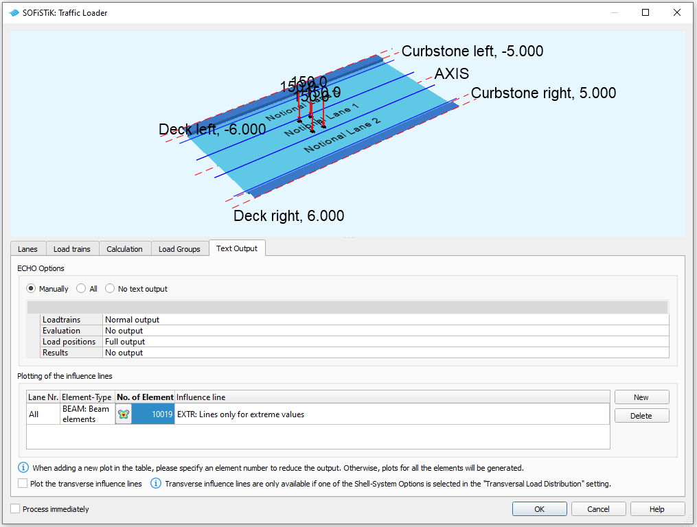
Define the scope of the text output for the report created by the Task.
ECHO options#
Specify the scope of the output ranging from No ouput to Extensive output.
Plotting of influence lines#
Add a new selection of influence lines for the plots in the report by clicking on the New button.
Select for which Lane Nr., Element-Type, Element No. the influnece lines are to be plotted.
Note
It is recommended to plot only the influence lines for a selection of elements numbers, otherwise the report can become quite large.