Shear Wall Design#
The task offers the possibility to perform the (preliminary) design for shear walls.
This chapter of the documentation focuses on the user input with the graphical user interface.
See also
Find out more about the theoretical principles of the shear wall design in the respective chapter of this documentation.
Tab General#
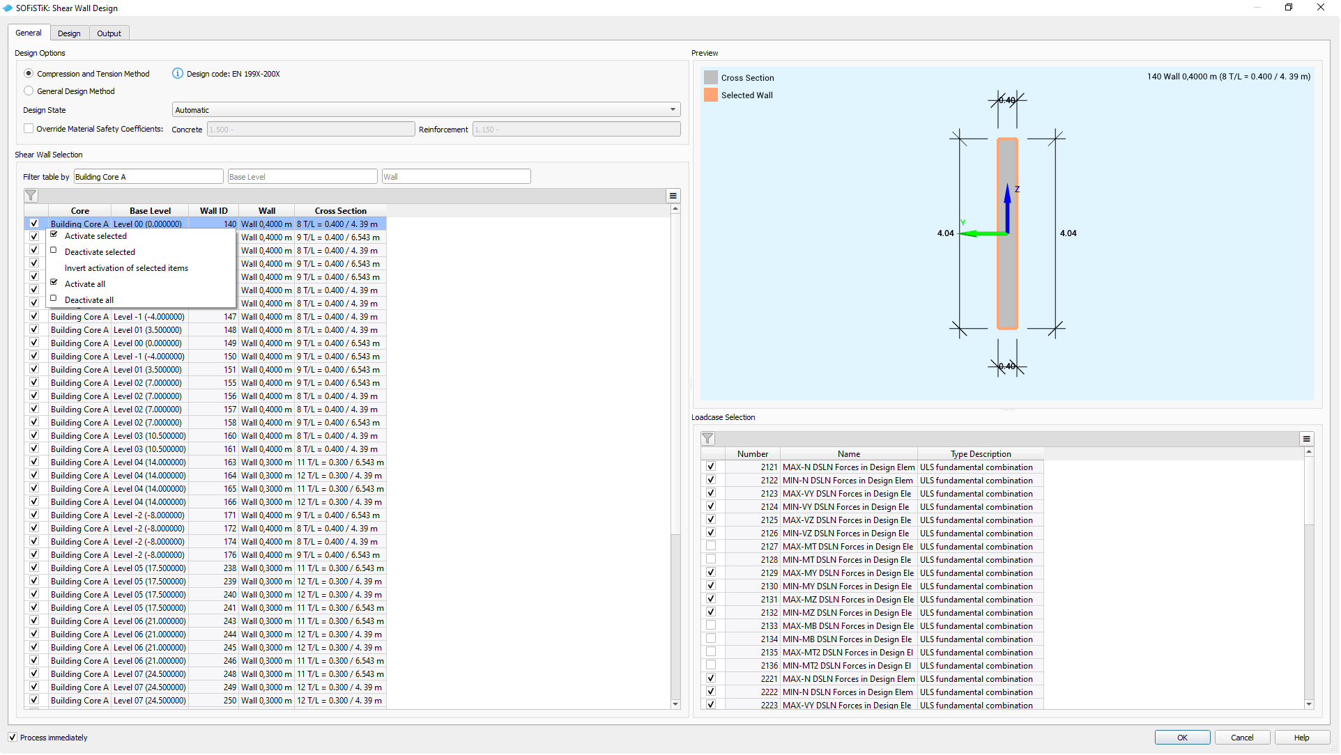
GUI Task Shear Wall Design - General Tab#
Design Options#
Select between the following two design methods:
Choose which Design State is applied:
Defaults to
Automatic, where the design state and the material safety factors are determined by the load combination type.It is possible specify the design state independently from the load combination type.
Additionally, you can override the Material Safety Coefficients for concrete and reinforcement. Without manual override, the values are taken from the
.inifile of the selected design code for the project.
Shear Wall Selection#
Select the walls for the shear design.
Note
The General Design Method requires the new cross section type Shear Wall.
Hint
Use the filter above to facilitate the selection of walls, e.g., all walls associated with a building core.
A right-click menu allows to (de-)select all rows at once
See also
Command reference of ![]() SOFiSTiK Analysis + Design for the definition of Building Cores.
SOFiSTiK Analysis + Design for the definition of Building Cores.
Preview#
The interactive viewer shows the selected wall with its dimensions, orientation in the project and the assigned cross section, if available.
The local coordinate system belongs to the design element and its cross section, indicating the location of the edge zones.
Load Case Selection#
Select the load cases used in the design for shear walls. The load case table is filtered for relevant load cases containing design element results. By definition, only load cases for the superpositioning of normal force, shear forces and bending moments, are considered for the design and automatically selected.
The task supports the following design combinations:
(D) |
ULS fundamental combination |
(A) |
ULS accidental combination |
(E) |
ULS seismic combination |
Tab Design#
Depending on the choice under , this tab presents itself differently and allows for design method specific input.
See also
Find out more about the theoretical principles, specifically regarding the Compression and Tension Method, General Design Method and Required Shear Reinforcement in the respective chapters of this documentation.
Compression and Tension Method#
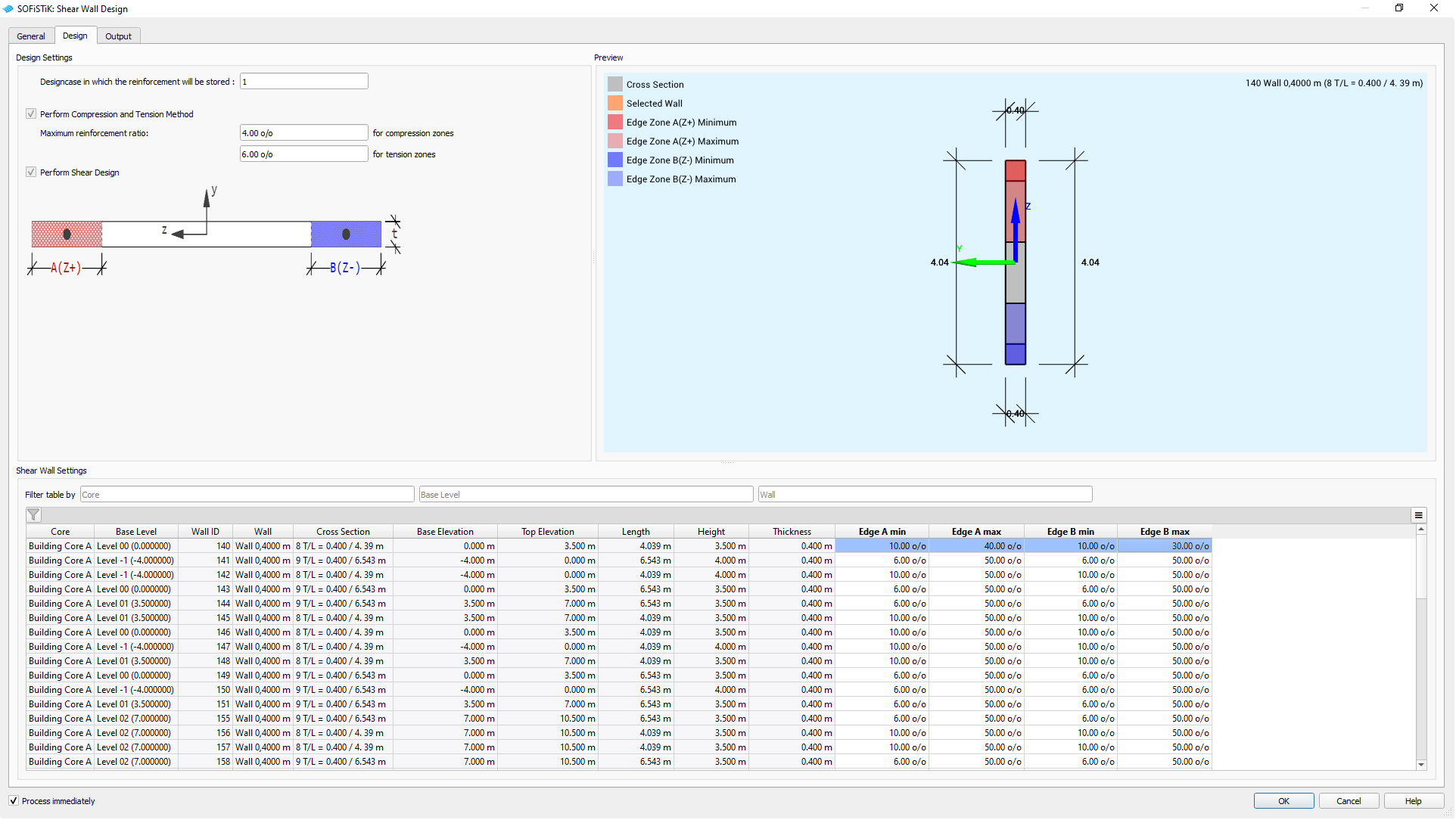
GUI Task Shear Wall Design - Design Tab for C&T-Method#
Design Settings#
Set the general design parameters by defining the maximum reinforcement ratio for the individual edge zones.
Shear Wall Settings#
Define the edge zones for each wall by determining the minimum and maximum length for each zone.
Parameter |
Description |
Default |
Range |
|---|---|---|---|
Min |
Minimum length: Starting Point for iteration of C&T-Method |
0 % |
0-50 % |
Max |
Maximum length: End point for iteration of the C&T-Method |
50 % |
0-50 % |
Note
Setting minimum and maximum length to the same value results in a fixed edge zone length.
Hint
It is possible to copy-paste cell values with
CTRL+CandCTRL+VTo copy multiple values, make sure to match ranges for source and target
Preview#
The interactive viewer shows the selected wall with its dimensions, orientation in the project and the assigned cross section, if available.
The local coordinate system belongs to the design element and its cross section, indicating the location of the edge zones.
By definition Edge Zone A is located in positive local z-direction.
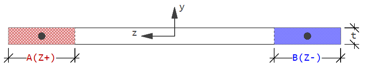
GUI Task Shear Wall Design - Edge Zone Definition#
General Design Method#
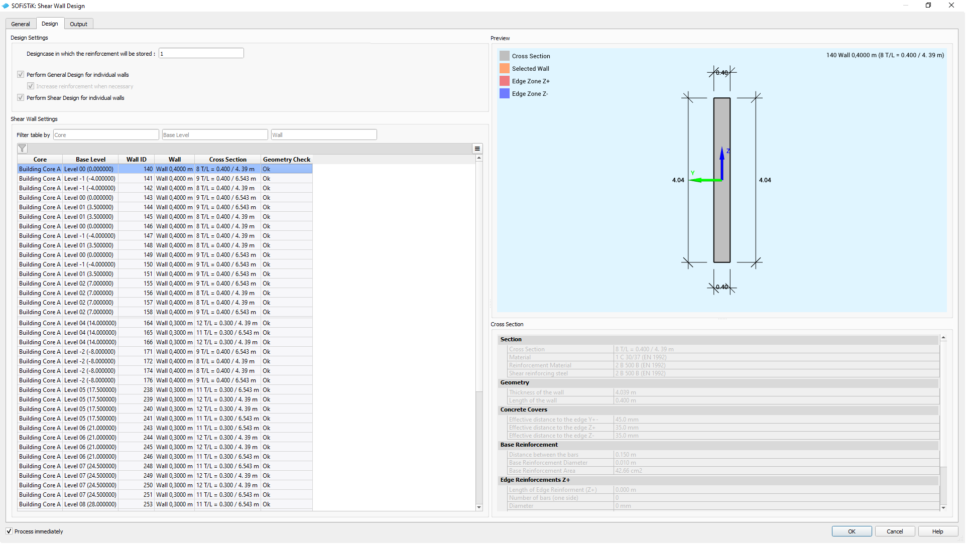
GUI Task Shear Wall Design - Design Tab for General Design Method#
Design Settings#
Shows the scope of the general design setting.
Shear Wall Settings#
Lists the selected shear walls and displays the following results:
Geometry Check
Provides a quick overview, for which walls a
Mismatchbetween the underlying wall and the referenced cross section for the design element.To be continued …
Preview#
The interactive viewer shows the selected wall with its dimensions, orientation in the project and the assigned cross section.
The local coordinate system belongs to the design element and its cross section, indicating the location of the edge zones.
Cross Section#
Shows the relevant information of the assigned cross section for the selected wall, indicating if it has edge reinforcement etc.