Rebar Check#
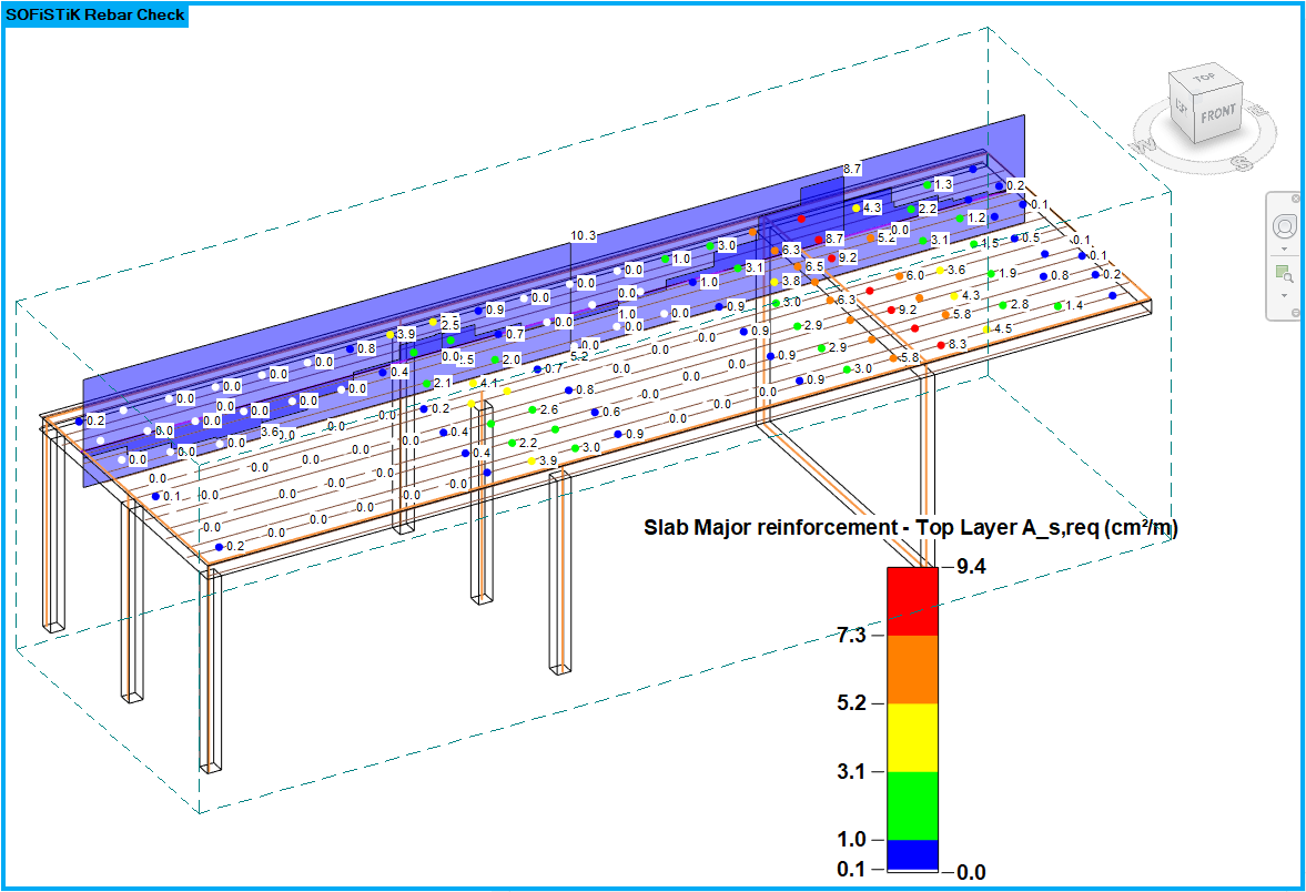
Allows comparison of drawn reinforcement with design results for slabs and columns. The check can be visualised with point- or cutline-based Display Styles. The Rebar Check is meant to gain a quick, rough overview about the required and provided reinforcement. The conscientious inspection of the reinforcement for structural and static details remains the user’s responsibility.

General#
Select within the SOFiSTiK: Rebar Check panel desired results by picking Data source resp. Design case. Display pattern contains default visualisation styles, the further options give possibility to configure the view in more detail. With Reload all results and cutline diagrams get refreshed.
Rebar Check: Slabs#
The point-based Rebar Check colourizes calculated results according to the chosen evaluation type on slabs. The major direction of the reinforcement must be aligned with the span direction of the corresponding analytical panel.
Following options are available:
Title |
Options |
Description |
|---|---|---|
Reinforcement orientation |
top major
top minor
bottom major
bottom minor
|
choose the desired orientation to check |
Evaluation type |
as,prov
as,req
as,req - as,prov
|
show drawn reinforcement
show design results
show spread between required & provided reinforcement
|
Display Style |
SOFiSTiK Rebar Check Points |
choose, create or edit a Display Style |
Scaling direction vector |
[0 - 10] |
scale the display of the orientation of the analytical panels,
disabled by setting value to zero
|
Distance factor result values |
[1 - 100] |
controls the density of result values to be shown |
Anchoring factor |
[1 - 100] |
estimates the anchoring length of rebars based on the diameter |
Further information about Anchoring factor
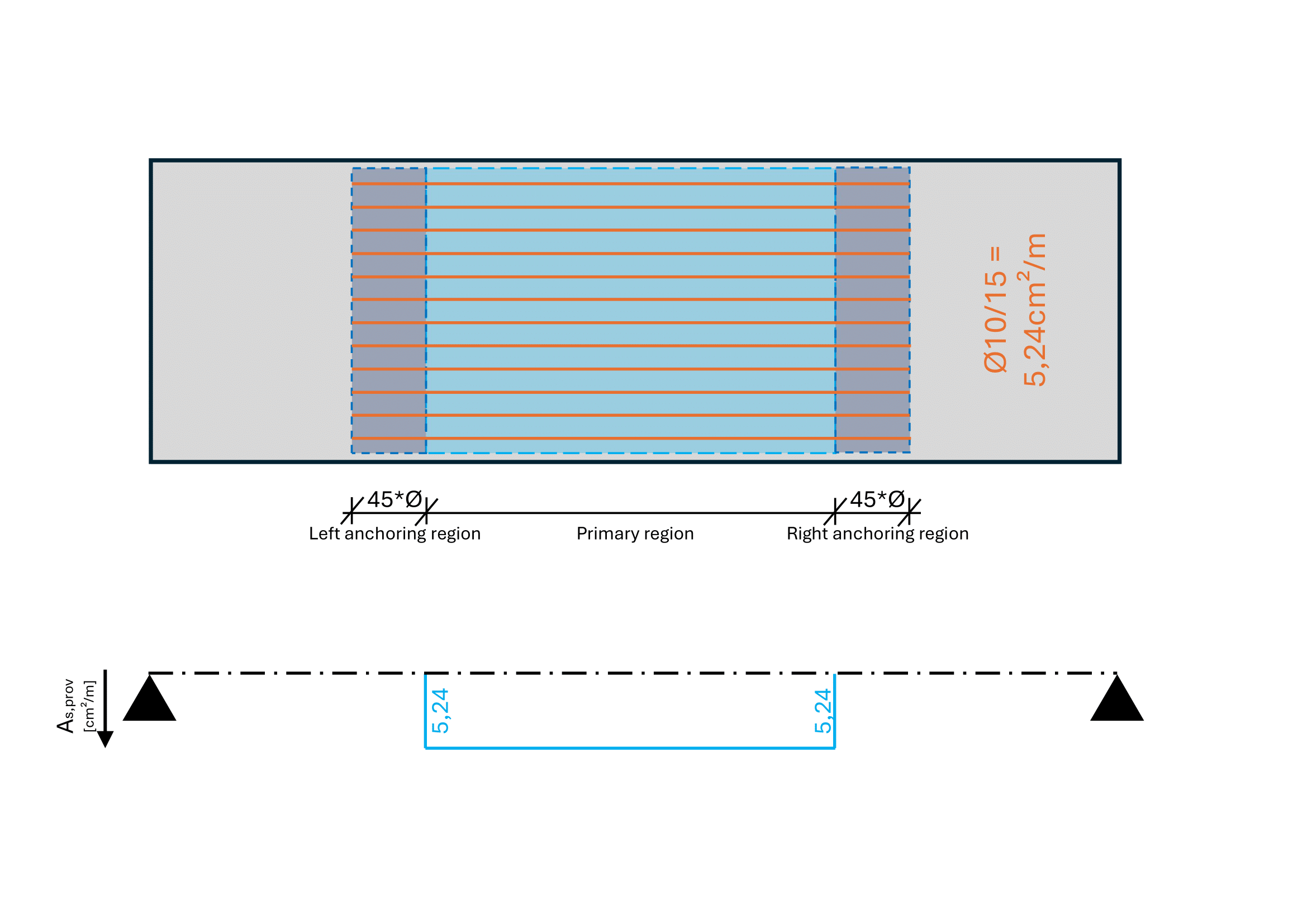
Anchoring factor is used to determine overlapping and supplementary reinforcement. It corresponds to the basic required anchorage length lb,rqd in relation to the diameter. The default value 45 is derived from C20/25 concrete in good bonding:
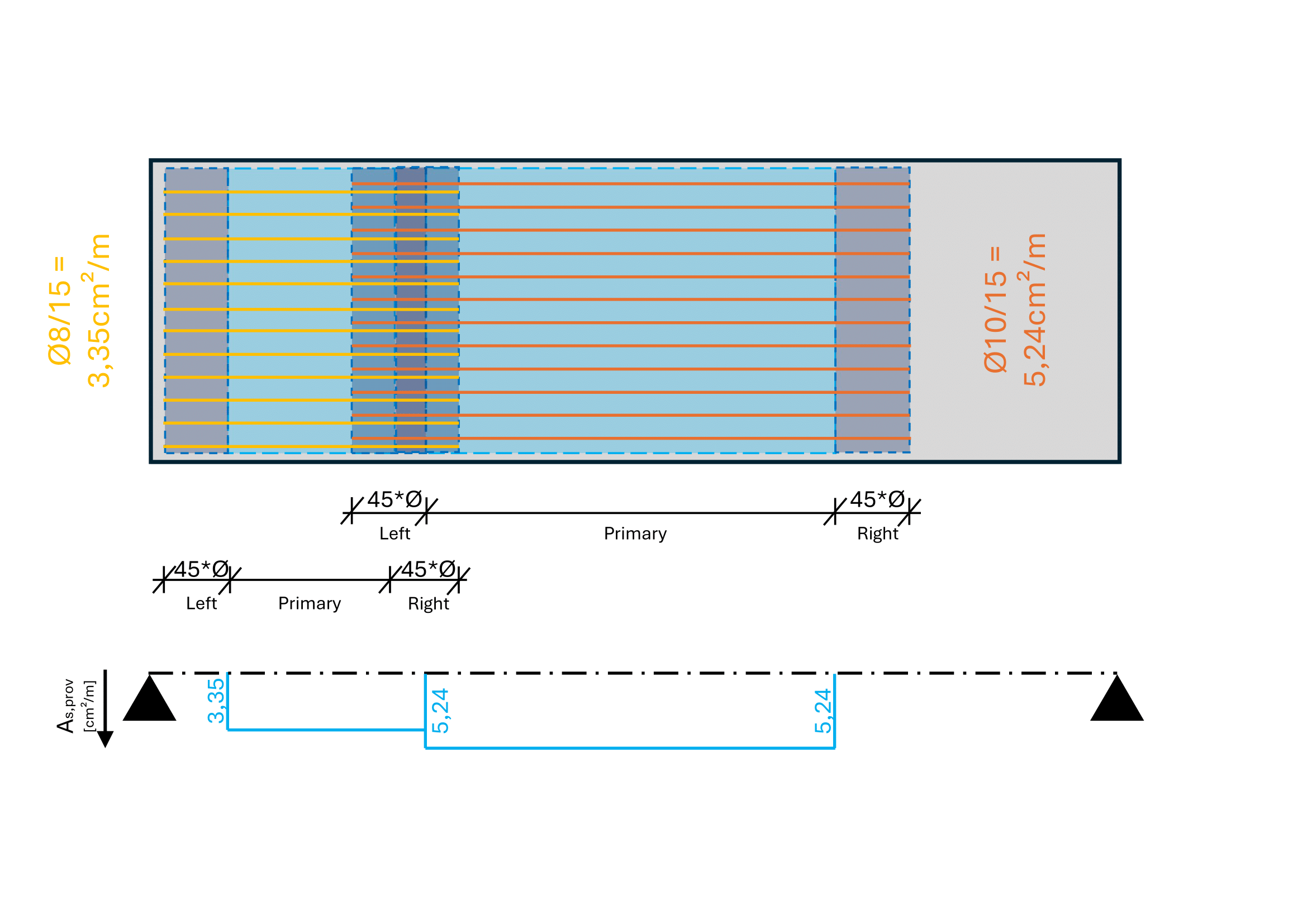
The main concept to identify the role of reinforcement relies on dividing it into three segments: Left/right anchoring regions and primary, middle regions. Inside the anchoring regions, the tensile strength in the bars needs to build up through bonding with concrete. In the middle regions the tensile strength is fully available.

If there are other rebars overlapping in the left or right regions each result point will be individually evaluated. Overlapping left/right regions with different diameters (or spacing) will return the lower as,prov value.

By using hooks, the anchoring region will be reduced to zero. This method offers the possibility to gain a quick, rough overview on provided reinforcement; structural and static details are not taken into account.
Rebar Check with Cutlines#
The diagram based Rebar Check offers another way to compare required and provided reinforcement in slabs.
Note
Cutlines need to be drawn as a model line with line style “SOF_ResultCutLine” in the working plane of the analytical panel. It is recommended to use the command “Result Cut Line”.
The following options are available:
Title |
Options |
Description |
|---|---|---|
Reinforcement orientation |
major
minor
|
choose the desired orientation to check |
Evaluation type |
as,prov
as,req
as,prov & as,req
as,req - as,prov
|
displays drawn reinforcement
displays design results
overlays drawn reinforcement & design results
show spread between required & provided reinforcement
|
Display Style |
SOFiSTiK Rebar Check Diagram |
choose, create or edit a Display Style |
Flip diagram |
on / off |
flips the display orientation (e.g. plan views) |
Rebar Check : Columns#
The diagram based Rebar Check colourizes calculated results according to the chosen evaluation type in columns.
The following options are available:
Title |
Options |
Description |
|---|---|---|
Reinforcement type |
longitudinal
shear
|
choose the desired type to check |
Evaluation type |
as,prov
as,req
as,prov & as,req
as,req - as,prov
utilization factor
|
display drawn reinforcement
display design results
overlay drawn reinforcement & design results
show spread between required & provided reinforcement
show utilization as,req / as,prov
|
Display Style |
SOFiSTiK Rebar Check Diagram |
choose, create or edit a Display Style |
Flip diagram |
on / off |
flips the display orientation (e.g. plan views) |
See also
The appearance (e.g. font sizes) of the predefined Display Styles may vary depending on the template file used and the language settings. Display Styles can be customized individually, see also Online Documentation of Autodesk® Revit®