General Explanations for Actions and their Categories in the Superposition Process#
Introduction#
This document provides some explanations for the use of actions and their categories in the program MAXIMA.
Theoretical Background#
For the European countries the several actions are defined in the EN 1990 and their corresponding National Annexes and for Switzerland in the SIA 260. These design codes superimpose the actions according to the partial factor method.
In these codes actions are given with categories in order to consider the different combination coefficients for the individual imposed loads.
In this tutorial the use of the categories for buildings is described.
Important
Please note, that preset actions with their categories for the selected design code are available for buildings and for bridges. Preset action combinations are only available for buildings. However, the SOFiSTiK workflow for the more complex action combinations for bridges is done with the program CSM - Construction Stage Manager or the CSM task in the SSD. This is not a part of this tutorial.
EN 1990 and its National Annexes#
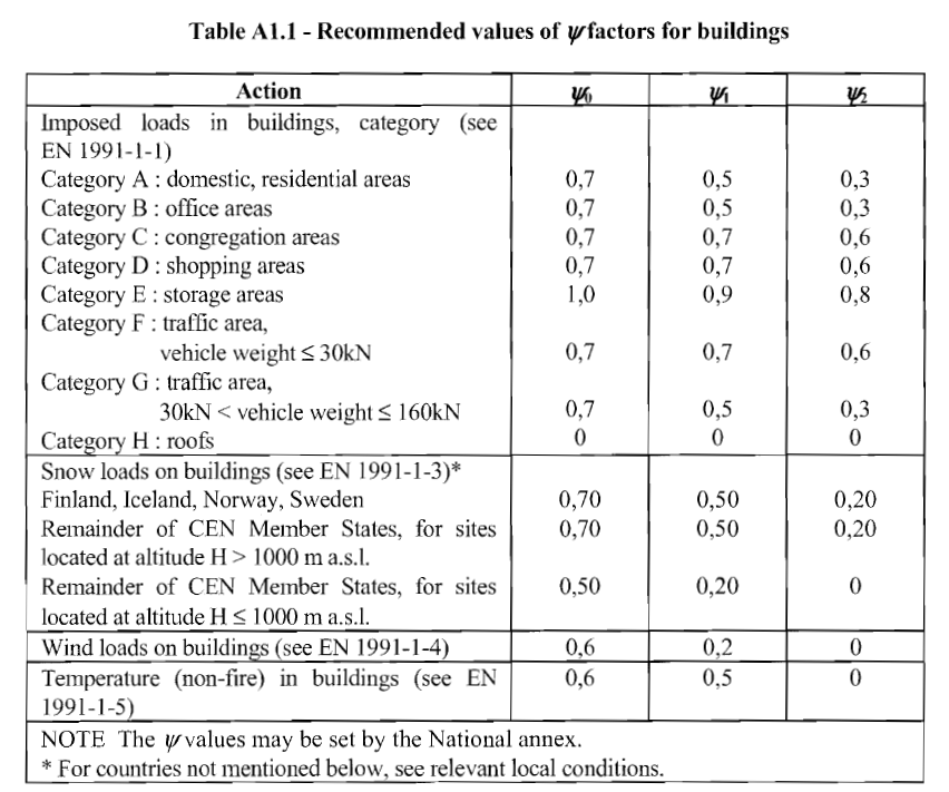
The combination coefficients are given in the table A1.1 of the EN 1990.
Literature: EN 1990 Eurocode - Basis of structural design
Important
Please note, given coefficients may be defined differently in the National Annexes.
SOFiSTiK offers for the selected design code of the National Annex the preset actions with their categories of the corresponding National Annex of the EN 1990.
SIA 260#
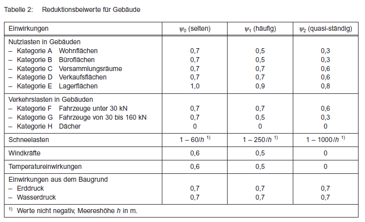
Analogous to the EN 1990, the SIA 260 specifies the coefficients in the table 2 of the annex A. The preset actions with their categories are available when selecting SIA 262 for concrete structures or SIA 263 for steel structures.
Literature: SIA 260 - Grundlagen der Projektierung von Tragwerken
Consideration of the Categories in the Superposition Process#
Important
Categories are always assigned to an action. That means, in the superposition process all categories of an action act together in order to determine the leading or accompanying actions.
E.g. the categories A, B, C, D and E of the imposed loads contain to the action Q. In the SOFiSTiK worklow they are called Q_A, Q_B, Q_C, Q_D and Q_E.
The categories F, G, H have a specialty. Since the experts disagree on whether these categories act together with A,B,C,D and E or not, SOFiSTiK offers two workflows:
1st possibility: The categories F, G, H acts togehter with the other categories. Therefore they are a part of the action Q and called Q_F, Q_G and Q_H. Only the action Q which includes the categories can be leading or accompanying action.
2nd possibility: The categories F, G, H acts not together with the other categories. Therefore they are assigned to the action L and called L_F, L_G and L_H. In this case the act L is independent on the action Q during the superposition process.
Hint
Both possibilites lead to different superposition results if loads for the categories A, B, C, D, E and F, G, H are available!
Basics of the Program MAXIMA#
Using the program MAXIMA, SOFiSTiK offers various options for determining automatically or manually the design internal forces or load case combinations. Detailed information can be found in the tutorial: https://www.sofistik.de/documentation/2020/en/tutorials/superpositions/general-maxima/superposition_general-maxima.html
Requirements#
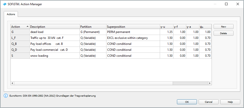
The actions have to be defined with the program SOFiLOAD record ACT or with the SSD task ‘Action Manager’. For each design code SOFiSTiK offers default actions with their categories which can be select in SOFiLOAD only with their designation or in the task ‘Action Manager’. Of course, user-specific actions with or without categories can also be defined. There have to be initial load cases with loads and their assignment to an action or category. These load cases should be calculated and results have to be available in the database.
Example#
For the following example there are two data sets:
an DAT file with MAXIMA definitions din_en1992-2004-slab-action-categories.dat
and the same information as an SSD file with the graphical definitions ssd2022-din_en1992-2004-action-categories.sofistik
Principle Workflow of the Example#
Generate the system inclusive the design code, materials, cross sections
Generate the actions with the task ‘Action Manager’ or with the program SOFiLOAD
Generate loads with the program SOFiLOAD
Run linear analysis
Generate action combinations in program MAXIMA (or in SSD task ‘Combinations’)
Generate superpositions (or SSD task ‘Superpositioning’)
System Definitions#
A simple 2D slab system is defined. Please note, that this system was only generated for demonstration purposes to show the superposition process. The used design code is DIN EN199X-200X for the National Annexes Germany.
Actions and Load Definitions#
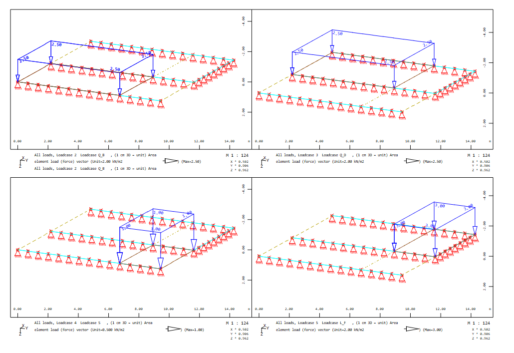
The slab system has four areas with different variable loads of different actions and categories in addition to the dead load of the action G. Following action with categories and load cases are defined:
Action G dead load with load case 1
Action Q category B Q_B pay load offices with load case 2
Action Q category D Q_D pay load commercial with load case 3
Action S snow with load case 4
Action L category F L_F traffic up to 30 kN with load case 5
Thus this example shows the above described 2nd possibility of using category F for action L.
The following picture shows the variable loads of the load cases 2 till 5:
For the preset actions and categories it is only necessary to input the action name. All other information about the preset actions are generated automatically.
+PROG SOFILOAD
HEAD Actions
ACT  'G'   TITL "dead load"
ACT  'Q_B' TITL "Pay load offices    cat. B"
ACT  'Q_D' TITL "Pay load commercial cat. D"
ACT  'S'   TITL "Snow loading"
ACT  'L_F' TITL "Traffic up to 30 kN cat. F"
END

+PROG SOFILOAD
HEAD Loads
LC   1 'G'   FACD 1 TITL "Loadcase G"
  AREA SAR '1' TYPE PG 1.5
  AREA SAR '2' TYPE PG 1.5
  AREA SAR '3' TYPE PG 2
LC   2 'Q_B' TITL "Loadcase Q_B"
  AREA SAR '1' TYPE PG 2.5
LC   3 'Q_D' TITL "Loadcase Q_D"
  AREA SAR '2' TYPE PG 2.5
LC   4 'S' 1 TITL "Loadcase S"
  AREA SAR '3' TYPE PG 1.0
LC   5 'L_F' 1 TITL "Loadcase L_F"
  AREA SAR '4' TYPE PG 3.0
ECHO ACT EXTR
END
The input of the actions in the SSD task ‘Action Manager’ is:
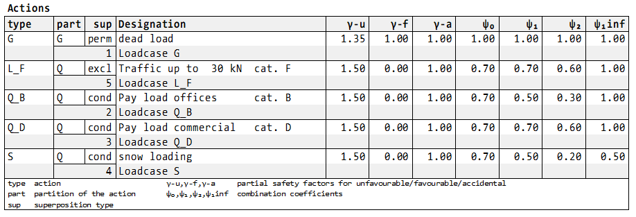
In connection with the input of the loads it is possible to set ECHO ACT FULL for the printout table of the used actions and the corresponding load cases:
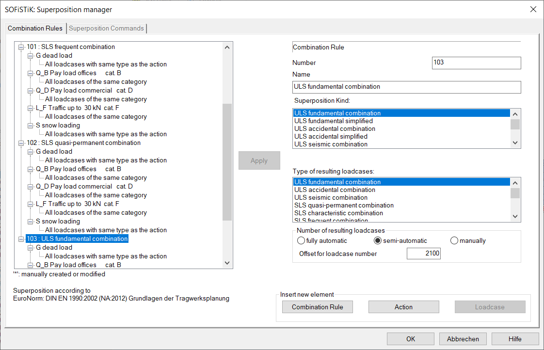
Action Combinations and Superpositions#
After the calculation of the single load cases the superpositions are done in order to get the necessary design values (e.g. internal forces and moments, support reactions etc.).
In the example files there are three action combinations available which also corresponds to the defaults:
Characteristic (rare) combination no. 100 for serviceability limit state
Frequent combination no. 101 for serviceability limit state
Quasi-permanent combination no. 102 for serviceability limit state
Fundamental combination no. 103 for ultimate limit state according to equation 6.10 EN 1990
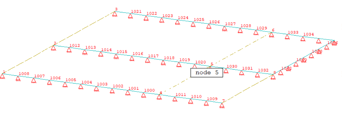
For the nodal support force PZ the full printout is requested in node no. 5. Here the determined leading and accompanying actions as well as the resulting factors are to be checked. In the node no. 5 all loads are active in the most unfavourable case for the support forces PZ.
The MAXIMA input is as follows:
+PROG MAXIMA urs:5
HEAD
ECHO TABS YES
!*!Label  Combinations
COMB NO 100 EXTR RARE BASE 1100 TYPE RARE TITL "SLS characteristic combination"
ACT  TYPE G
  LC NO 0
ACT  TYPE Q_B
  LC NO -1
ACT  TYPE Q_D
  LC NO -1
ACT  TYPE S
  LC NO 0
ACT  TYPE L_F
  LC NO -1

COMB NO 101 EXTR FREQ BASE 1200 TYPE FREQ TITL "SLS frequent combination"
ACT  TYPE G
  LC NO 0
ACT  TYPE Q_B
  LC NO -1
ACT  TYPE Q_D
  LC NO -1
ACT  TYPE S
  LC NO 0
ACT  TYPE L_F
  LC NO -1

COMB NO 102 EXTR PERM BASE 1300 TYPE PERM TITL "SLS quasi-permanent combination"
ACT  TYPE G
  LC NO 0
ACT  TYPE Q_B
  LC NO -1
ACT  TYPE Q_D
  LC NO -1
ACT  TYPE S
  LC NO 0
ACT  TYPE L_F
  LC NO -1

COMB NO 103 EXTR DESI BASE 2100 TYPE DESI TITL "ULS fundamental combination"
ACT  TYPE G
  LC NO 0
ACT  TYPE Q_B
  LC NO -1
ACT  TYPE Q_D
  LC NO -1
ACT  TYPE S
  LC NO 0
ACT  TYPE L_F
  LC NO -1

!*!Label Superpositions
SUPP COMB 100 EXTR MAMI ETYP QUAD TYPE MXX,MYY,MXY,VX,VY TITL " Forces in Quadrilateral Elements"
SUPP COMB 100 EXTR MAMI ETYP QNOD TYPE MXX,MYY,MXY,VX,VY TITL " Forces in Nodes"
SUPP COMB 100 EXTR MAMI ETYP BOUN TYPE PZ TITL " Distributed Forces along Nodes"
SUPP COMB 100 EXTR MAMI ETYP NODE TYPE UZ,URX,URY TITL " Nodal Displacements"

SUPP COMB 101 EXTR MAMI ETYP QUAD TYPE MXX,MYY,MXY,VX,VY TITL " Forces in Quadrilateral Elements"
SUPP COMB 101 EXTR MAMI ETYP QNOD TYPE MXX,MYY,MXY,VX,VY TITL " Forces in Nodes"
SUPP COMB 101 EXTR MAMI ETYP BOUN TYPE PZ TITL " Distributed Forces along Nodes"
SUPP COMB 101 EXTR MAMI ETYP NODE TYPE UZ,URX,URY TITL " Nodal Displacements"

SUPP COMB 102 EXTR MAMI ETYP QUAD TYPE MXX,MYY,MXY,VX,VY TITL " Forces in Quadrilateral Elements"
SUPP COMB 102 EXTR MAMI ETYP QNOD TYPE MXX,MYY,MXY,VX,VY TITL " Forces in Nodes"
SUPP COMB 102 EXTR MAMI ETYP BOUN TYPE PZ TITL " Distributed Forces along Nodes"
SUPP COMB 102 EXTR MAMI ETYP NODE TYPE UZ,URX,URY TITL " Nodal Displacements"

SUPP COMB 103 EXTR MAMI ETYP QUAD TYPE MXX,MYY,MXY,VX,VY TITL " Forces in Quadrilateral Elements"
SUPP COMB 103 EXTR MAMI ETYP QNOD TYPE MXX,MYY,MXY,VX,VY TITL " Forces in Nodes"
SUPP COMB 103 EXTR MAMI ETYP BOUN TYPE PZ TITL " Distributed Forces along Nodes"

!*!Label Superposition for nodal forces PZ with full printout node no. 5
ECHO LOAD,FACT
ECHO NODE P
SUPP COMB 100 EXTR MAMI ETYP NODE TYPE PZ FROM 5 TITL " Supporting Forces in Nodes"
SUPP COMB 101 EXTR MAMI ETYP NODE TYPE PZ FROM 5 TITL " Supporting Forces in Nodes"
SUPP COMB 102 EXTR MAMI ETYP NODE TYPE PZ FROM 5 TITL " Supporting Forces in Nodes"
SUPP COMB 103 EXTR MAMI ETYP NODE TYPE PZ FROM 5 TITL " Supporting Forces in Nodes"
END
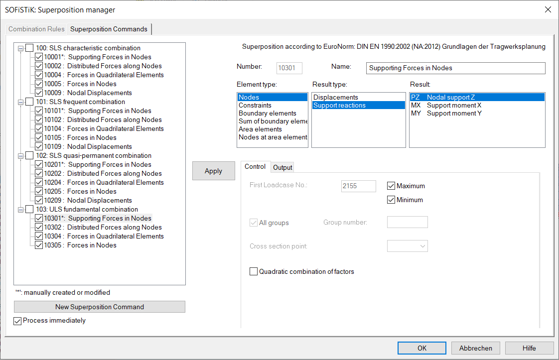
Or in the SSD the action combinations are shown in the task ‘Define Combinations’ and the superposition values are shown in the task ‘Superpositioning’:
The printout starts with the general information about the used action combinations and resulting load case numbers, e.g.:
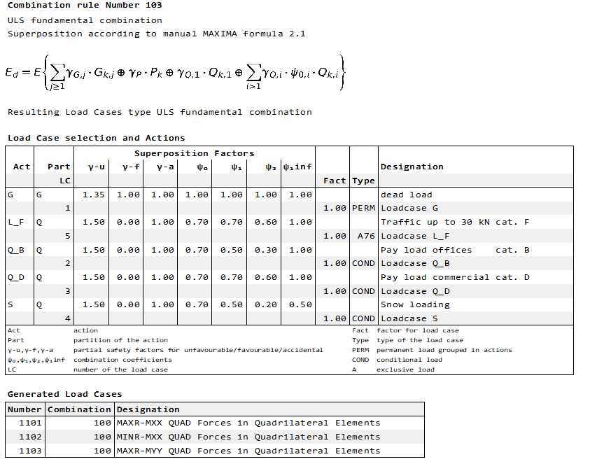
The explicitly requested full printout of the superposition of the nodal support value PZ in node no. 5 follows. Finally, the full printout will be explained for the minimum nodal support force PZ in node no. 5 for the combination 103 - ULS fundamental combination:
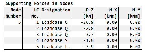
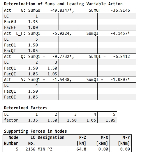
The first table shows the values of the initial load cases. In the second table ‘Determination of Sums and Leading Variable Action’ the calculated sums and the possible resulting factors are printed. Here the decision for the leading or accompanying action is shown with a * at the corresponding sum value. As decribed above the load cases 2 and 3 of the action Q with categories B and D acts together. Therefore the action Q is the leading action. Although the action L with category F has the lowest individual value PZ in load case 5, it is only an accompanying action.
Hint
Please note, that the leading action is that with the largest difference between the two sums.
Calculation of action L_F:
SumQ1 = gam-u * PZ LC 5 = -5.9224
SumQI = gam-u * psi0 * PZ LC 5 = -4.1457
Difference = 1.7767
Calculation of action Q with the categories Q_B and Q_D:
SumQ1 = gam-u * PZ LC 2 + gam-u * PZ LC 3 = -9.7732
SumQI = gam-u * psi0 * PZ LC 2 + gam-u * psi0 * PZ LC 2 = -6.8412
Difference = 2.932 = leading action
Calculation of action S:
SumQ1 = gam-u * PZ LC 2 = -1.5438
SumQI = gam-u * psi0 * PZ LC 2 = -1.0807
Difference = 0.4631
It follows the table of the determined load case combination with the determined factors for minimum PZ. At least the resulting nodal support forces min PZ = -64.8 kN is shown in the table ‘Supporting Forces in Nodes’
Remarks#
The National Annexes of the EN 1990 and SIA 2060 provide different formulas for the action combinations with different combination coefficients for the actions and their categories. SOFiSTiK offers several options for the superposition automatically or manually using action combinations and for the determination of resulting load case combinations. It is the task of the engineer to check the used combination rules and randomly the results with the extensive output only for a specific element.
If you need a special solution for the topic of the combinations and superpositions of your project, contact us please with an email to support@sofistik.com.