Post Tensioned Concrete Beam Bridge - Fatigue Design#
Introduction#
This tutorial is an add on to the “Post Tensioned Concrete Beam Bridge” Tutorial. The main objective is to describe the workflow how to performe a fatigue design.
Note
An advanced SOFiSTiK knowledge including TEDDY input language is required for this tutorial. You need to be familiar with the tutorial “Post Tensioned Concrete Beam Bridge” as well.
Objectives#
Live load analysis including Fatigue Load Model FLM3
Fatigue Design
All other workflow steps are equal to the steps described in the General Workflow description and in the Post Tensioned Concrete Beam Bridge tutorial.
Project Description#
For a detailed project description see the Post Tensioned Concrete Beam Bridge tutorial.
Actions#
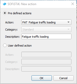
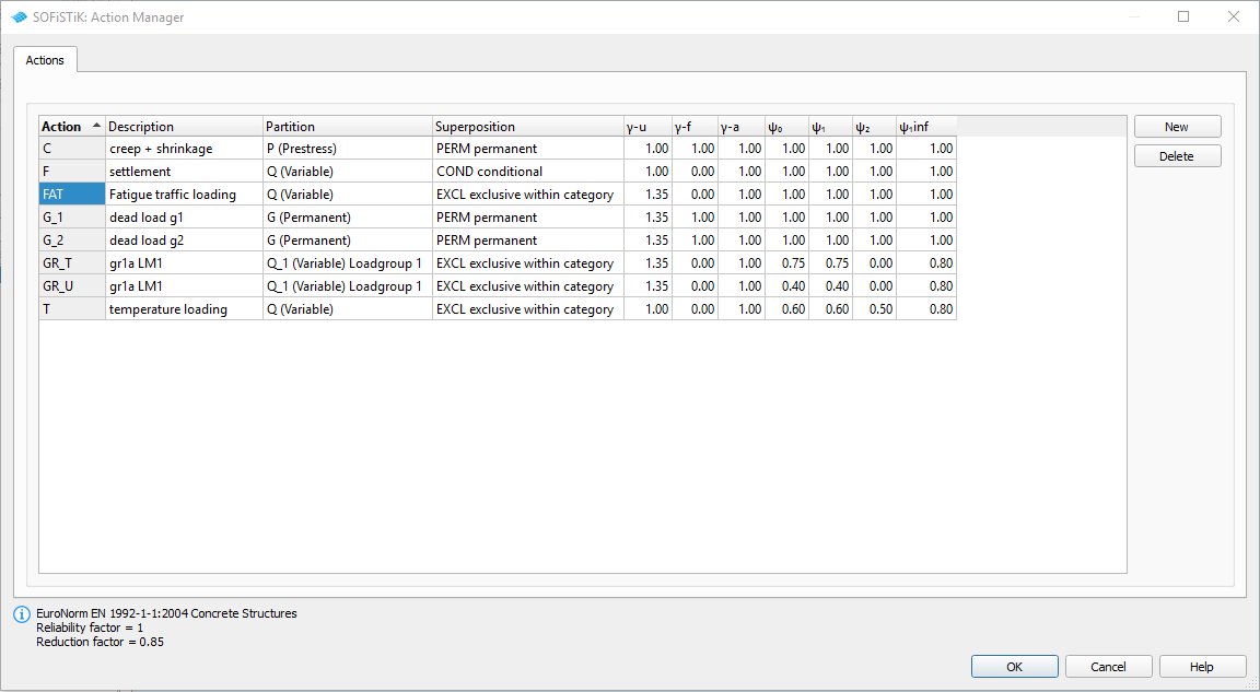
To perform the fatigue design we need to define a new user defined action FAT inside the load case manger of SOFiPLUS.
Generate Envelope from Traffic Loads#
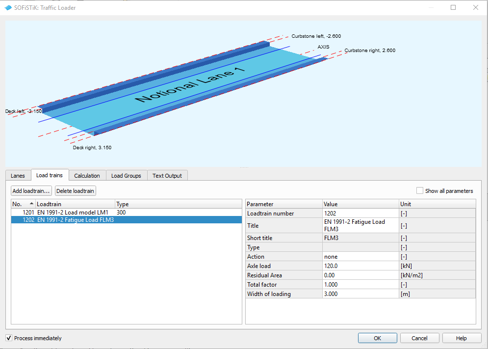
The workflow is the same as already explained in the Post Tensioned Concrete Beam Bridge tutorial. For the fatigue design it is necessary to define a new load train representing the Fatigue Load Model 3 = FLM3 from the eurocode. This can be done inside the SSD task “Traffic Loader”. Please add a new load train inside the tab “Load Trains”
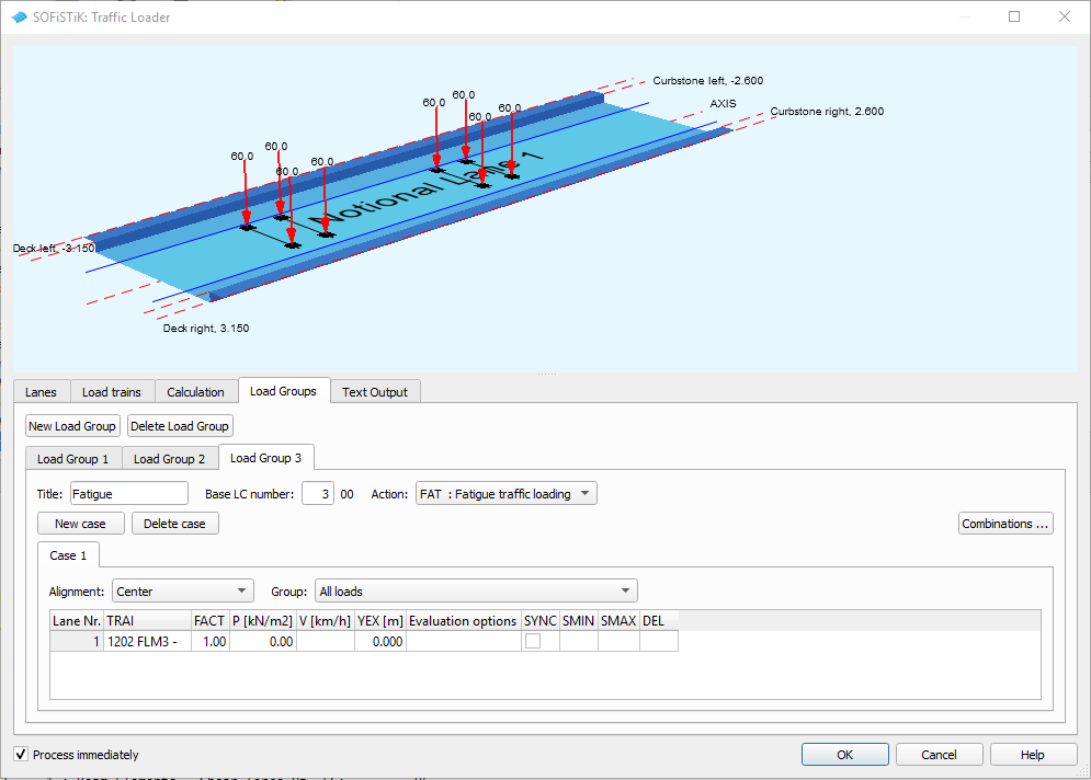
Next you define a new load group and define the evaluation cases. In our case we want an evaluation of the FLM3 from the center lane. Please see the following picture with the corresponding input.
Fatigue Design#
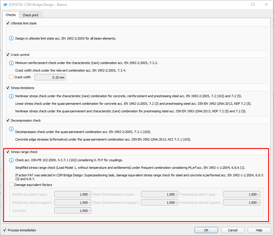
Inside the task “”CSM Bridge Design - Beams”” you can also select fatigue design checks, which enables you to perform them in an easy way.
Fatigue Design (manually)#
Just for information here we describe the manual workflow with a “Text Editor (TEDDY)” task. Based on the regulations of the eurocode, it is necessary to define design combinations including forces and moments from permanent loads, prestressing, creep and shrinkage and also from temperature and settlement loads. This forces and moments will be combined with the results from the FLM3 model. now we face the problem, that we have 8 temperature loads and 3 settlement loads. The fatigue design must be checked for every possible combination. That means we will have 8 x 3 = 24 design combinations. For the calculation of damage equivalent stress ranges for steel verification, the axle loads of fatigue load model 3 shall be multiplied by the following factors:
1,75 for verification at intermediate supports in continuous bridges
1,40 for verification in other areas.
We deal with that problem by defining the factors manually inside the AQB combinations. For the necessary treatment of the damage equivalent factor for fatigue λ_s, according to Annex NN of EN 1992-2:2005, there is a special input within the BEAM record. Please see the principle TEDDY input for the bridge superstructure of group 20:
+prog aqb urs:desi10 $ fatigue design mid span
head fatigue design mid span
$ detailed design with load model flm3:
$ *************************************************************
echo forc,stre,nstr,sect,rein,comb,shea,lc,crac,desi,usep no
echo usep yes

ctrl svrf   1.00000 $ take into account reinforcement for c+s


!*!label factors for ?_s
$ damage equivalent factor for fatigue ?_s according annex nn en 1992-2:2005
let#phi  1.2               $ is the damage equivalent impact factor controlled
                           $ by the surface roughness from 1.2 to 1.4

let#k2   1/7               $ is the slope of the appropriate s-n-line to
                           $ be taken from tables 6.3n and 6.4n of en 1992-1-1

let#lam1 1.30,1.06         $ beiwerte spannstahl/bewehrung im feld

let#lam2 0.92*(3.0/2)**#k2 $ is a factor that takes into account the traffic volume.
                           $ n_obs = 3.0 mio vehicles/year

let#lam3 (90/100)**#k2     $ is a factor that takes into account the design life of the bridge.
                           $ n_years = 90

let#lam4 (1/1)**#k2        $ is a factor to be applied when the structural element is loaded
                           $ by more than one lane.

$
!*!label loadcases to be used:
#include $(project)_csmlf.dat  $ aqb lc-loadcase definition of construction stages gpc
  $ block can also be used separate,     $ see csm.dat\english\more\csm31_design_maxi.dat
  $ the following lc lines can also bei added with #include aqb_lc_act and  #include aqb_lc_gpc
  $ via file  ..._csmlf.dat - see also csm ctrl incl 0/1
lc       type 'f'     cst 9998 ref gros
lc       type 't'     cst 9998 ref gros
lc       type 'fat'   cst 9998 ref gros
$

!*!label lambda factors for beam elements
beam from grp 20 $$
 lamt #phi*#lam1(0)*#lam2*#lam3*#lam4 $$ tendons
 lams #phi*#lam1(1)*#lam2*#lam3*#lam4 $$ reinforcing steel
 laml #phi*#lam1(1)*#lam2*#lam3*#lam4 $$ reinforcing steel stirups
 lamc 1.0                             $$ correction factor concrete for railway bridges
   cs auto
$
!*!label reinforcement distribution
rein  lcr    1 rmod accu    $ use reinforcement distribution from csm bridge design - beams as minimum reinforcement
rein  lcr    2 rmod sing    $ save necessary reinforcement from fatigue design in new reinforcement distribution

$ combinations:
!*!label 2 loops for temperature and settlement load cases
loop#t 8 $ loop 1 over 8 tempearture load cases: lc 91 to lc 98
 let#lft 91
 loop#sf 3 $ loop 2 over 3 settlement load cases: lc 51 to lc 53
  $ variables
  let#lfsf 51
  let#lfsp1 20001+#t*100+#sf*10
  let#lfsp2 20002+#t*100+#sf*10
  let#lfsp9 20009+#t*100+#sf*10
      $ defines the permanenten part
  comb sum my titl 'fat_lm3_span_perm' lcst      - lc1 g lc2 pb  0.9 lc3 zp  1.0 lc4 c lc5 #lft+#t 0.6 lc6 #lfsf+#sf 1.0
      $ defines the maximum limit
  comb max my titl 'fat_lm3_span+'     lcst #lfsp1 lc1 g lc2 pb  0.9 lc3 zp  1.0 lc4 c lc5 #lft+#t 0.6 lc6 #lfsf+#sf 1.0
  comb and                                         lc1 fat 1.40 $ fatigue: factor mid span
  $ defines the minimum limit
  comb min my titl 'fat_lm3_span-'     lcst #lfsp2 lc1 g lc2 pb  0.9 lc3 zp  1.0 lc4 c lc5 #lft+#t 0.6 lc6 #lfsf+#sf 1.0
  comb and                                         lc1 fat 1.40 $ fatigue: factor mid span
  $ envelope
  comb gmax lcst #lfsp9 titl 'fat_lm3_span_max'

  echo fat extr  $ -> plot fatigue design results in report browser
  nstr fat en92  $ perform fatigue design
 endloop
endloop
end
The result can be checked with WINGRAF, with Result Viewer and inside the Report Browser.