Thermal Analysis of a Steel Section (arbitrary)#
Introduction#
This tutorial deals with the Thermal Analysis of an arbitrary Steel Section. The geometry of the cross section is entered graphically via cross-section editor CSE in SOFiPLUS.
Note
A basic SOFiSTiK knowledge is required for this tutorial. Inside this tutorial we show only the project specific workflows, which are different from the basic workflow.
Objectives#
Define Cross Section via CSE
Prepare edges for fire loads
Project Description#
Material#
Number |
Title |
Class |
|---|---|---|
1 |
Structural Steel |
S 235 |
Cross sections#
Number |
Title |
Dimensions |
|---|---|---|
2 |
Rolled Steel |
SHS 300 x 300 x 12 |
Design code#
This tutorial is based on Eurocode DIN EN 1993.
Step by Step Instructions#
Project Overview#
Create a new SSD project based on DIN EN 1993
Create the required materials
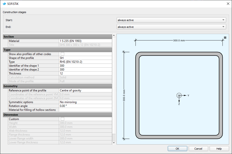
Create a new solid cross section with task
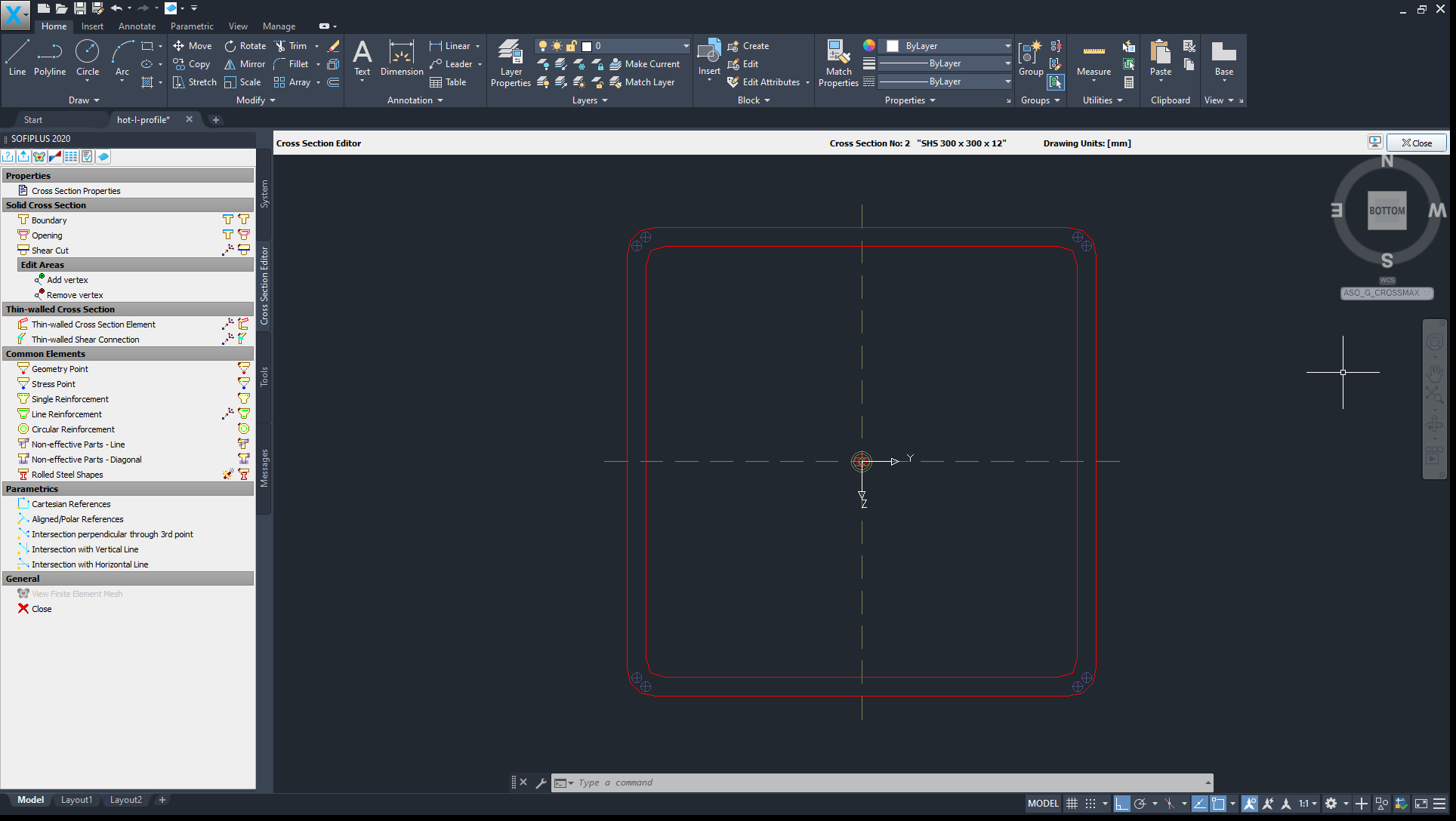
Generate Cross Section inside SOFiPLUS with Cross Section Editor
Insert a standard rolled steel profile into the current section
For Fire Design you have to save the mesh in a subdirectory
Save the section
In SSD insert the task
Define fire curve, time, protection class, etc.
With OK you can start the thermal analysis
Starting a new project#
See chapter Start New Project in General Workflow description.
Defining materials#
Generate all necessary materials listed above. Follow the procedures explained in chapter Material Definition in General Workflow description.
Defining cross sections#
Follow instructions in Thermal Analysis of a Steel Section (I-Profile) until opted for cross section selection.
Insert a standard rolled steel profile into the current section.

New Rolled Steel Shapes#
Insertion point is (0.00, 0.00)

SOFiPLUS(-X) - Cross Section Editor (click to enlarge)#
Preparing edges for fire loads#
Note
For I-profiles there are already predefined flammable edges (Z-,Z+,Y-…). For other steel profiles, these edges still need to be defined.
Use and select the steel section.
Define boundary properties for the edges to allow for later application of fire loads by and select edges relevant for the thermal analysis.
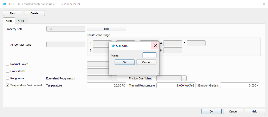
Click , enter a name and confirm with OK. Make sure to tick the box for ‘Temperature Environment’ in all property sets to initialize the edges for further calculation. The settings themselves will be handled in the task ‘Thermal Analysis’ in SSD.
Repeat the previous steps as many times as needed. Note that there are two approaches, both with their own advantages and disadvantages:
Method A:
Define two property sets ‘FIRE’ and ‘NONE’ and assign the appropirate sets to your edges depending on your needs.

SOFiPLUS(-X) - Extended Material Values (click to enlarge)#
Note
This approach is easier to set up, but requires to go back into Cross Section Editor whenever the flamed edges change.
Method B:
Define individual property sets for each edge, similar to the unchanged I-section.
Note
This approach is more work initially, but allows for more flexibility when flamed edges change because it can be done directly in the ‘Thermal Analysis’ task.
Defining fire load via thermal analysis#
The following steps are once again similar to Thermal Analysis of a Steel Section (I-Profile).