Steel Cross Sections Resistance#
The SSD task ‘’Steel Cross Section Resistance’’
contains following tabs:
Design
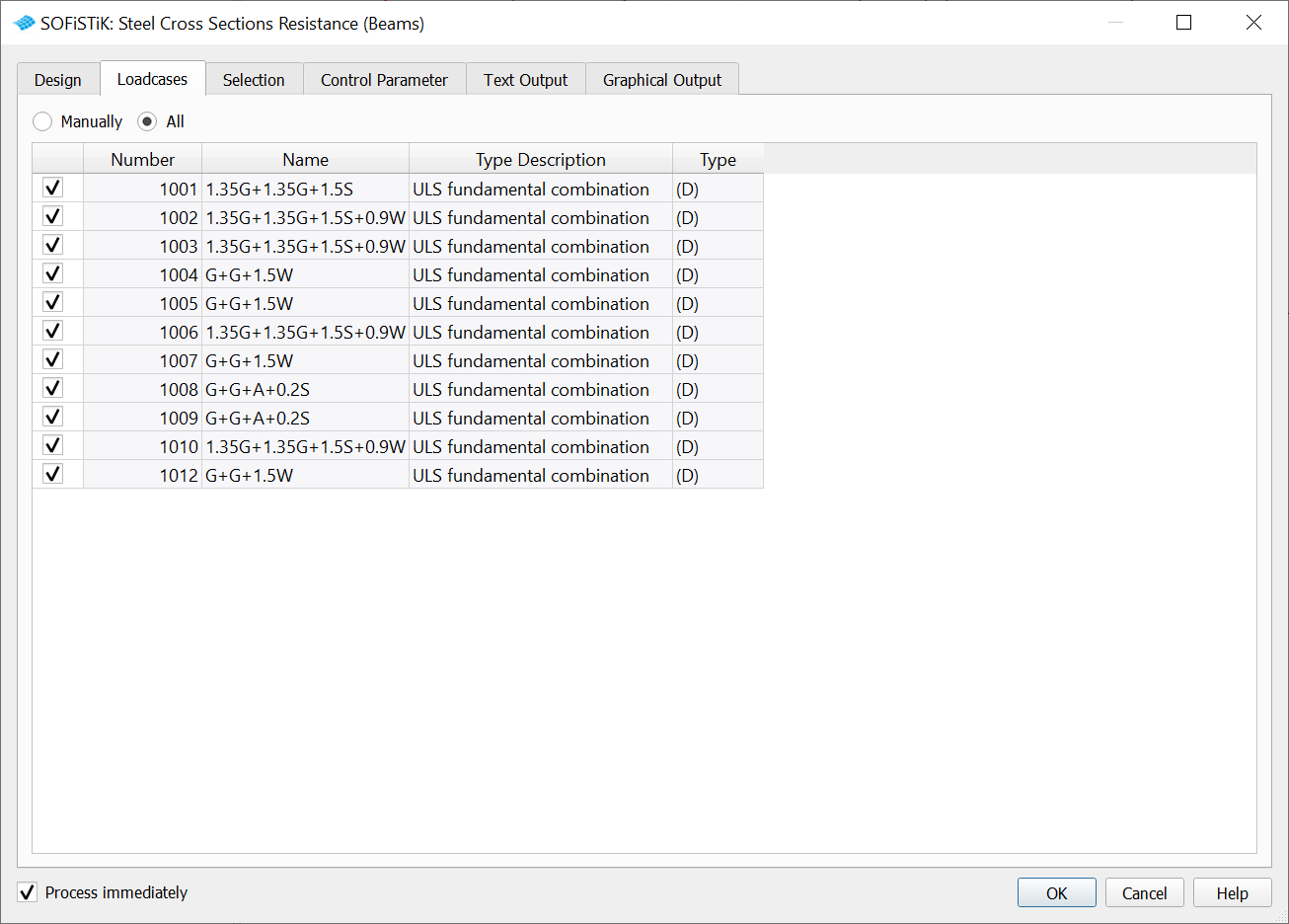
Loadcases
Selection
Control Parameter
Text Output
Graphical Output
Design#
The “Design case” number represents the loadcases for results (utilization results, cross-section classification etc.). You can also choose between the reduced output or detailed output for the Cross-Section Classification option. In the c/t tables you will find all necessary information regarding the cross-section classification (e.g. plates-stresses, plates-thickness, plates-length…).
The task provides 4 design methods:
Von Mises Yield Criterion
In case that the selected design code is part of Eurocode family, additionaly you may choose:
Linear Summation of Forces and Moments (EN 1993-1-1, 6.2.1 (7), Eq. 6.2)
Total Interaction of Forces and Moments (EN 1993-1-1, 6.2.8 - 6.2.10)
Nonlinear Stress with Strain Hardening
Choose a Design Method. As there exist several methods allowed, user may decide which Design Method should be decisive for a particular check:

Von Mises Yield Criterion#
This is the most general method and may be applied as a general cross-section check procedure. Even if some particular steel design code is not implemented in SOFiSTiK, you may use this general method. Stresses will be calculated and a stress-dependent cross-section class will be determined. Cross-sections of class 1-3 will be checked against Von Mises Yield Criterion while cross-sections of class 4 will be identified and marked in ‘’red’’ only.
The output values are written under σ-v (see Screenshot below, blue color).
An appropriate check will not be processed for class 4 cross-sections as this method is not suitable for this, i.e. only elastic resistance of cross-section will be considered.
Linear Summation of Forces and Moments#
This is a EN 1993-1-1 based cross-section check method. Same as during Von Mises Yield Criterion method, stresses will be calculated firstly, because they are needed to determine a stress-dependent cross-section class. Secondly, an automatic procedure will be applied - cross-sections of class 1-2 will be checked according to EN 1993-1-1, 6.2.1 (7) & Eq. 6.2; cross-sections of class 3 will be checked against Von Mises Yield Criterion and cross-sections of class 4 will be identified and marked in “red” only. Again, an appropriate check will not be processed for class 4 cross-sections as this method is not suitable for this. Therefore, cross-sections of class 1-2 will be checked plastically, cross-sections of class 3 elastically and no check will be performed for cross-sections of class 4.
Total Interaction of Forces and Moments#
This is also a EN 1993-1-1 based cross-section check method. The only difference to Linear Summation of Forces and Moments is that for the cross-sections of class 1-2 complex interaction formulas according to EN 1993-1-1, 6.2.8-10 will be applied. This allows for more economic design.
Note
Although only one of the methods Linear Summation of Forces and Moments or Total Interaction of Forces and Moments is chosen, the results will be printed for all 3 methods - this is useful, because you get an overview of all methods in one place and you may decide if the method you have chosen meets your expectations. The decisive value is marked in blue (if utilization level < 1.000) or in red (if utilization level > 1.000). The decisive value depends on the method which has been chosen.
Nonlinear Stresses with Strain Hardening#
This is also a EN 1993-1-1 based cross-section check method. This method is mostly intended to solve the cross-sections of class 4, when calculation of non-effective parts of cross-sections is required. This is made by applying an iterative solution. A true stress-strain curve of a material is used. It will be checked if the forces can be resisted by calculating internal forces with non-linear stress-strain curve. Only a warning, without an utilization level, will be printed, if the resistance is not sufficient.
Loadcases#
In this tab you fill find all available loadcases with an ULS (Ultimate Limit State) action :
Design (D),
Accidental (A) and
Earthquake (E).

Next steps are necessary to define an ULS (Ultimate Limit State) action Design (D), Accidental (A) or Earthquake (E)” loadcases.
Run the defined loadcases with the
Linear Analysis task.
Combine the loads with the
Combine Loads task, there you should select the type of the results “ULS - combination”.
Analyze the combined loadcases with the task
Analysis of Combined Loads.
Selection#
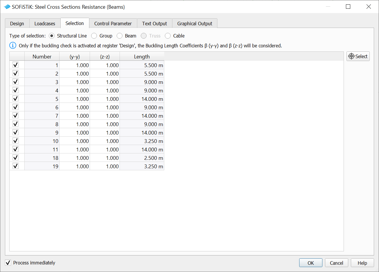
In the “Selection” tab per default the structural lines with a steel material will appear in the table.

The “Number” column represents the number of the structural lines.
Important
β values represent the buckling factor in (y-y) and (z-z) direction. The β factors will be taken into account only if the checkbox “Flexural Buckling” from the Design tab is checked. This feature will do the most simple centric buckling check. This feature is only for those customers who do not have a BDK license.
If you have a BDK license, then please use BDK (Steel Buckling Resistance task) for flexural buckling check!!!
The task provides 5 types of selection.
Structural lines,
Group of elements,
Beam elements,
Truss elements.
Cable elements.
In case ‘’structural lines’’ have been selected, then the type of the element must be ‘’beam’’.
If you need to check different types of elements (e.g. beam and trusses), then it is required to split the check into multiple tasks.
Control Parameter#
Maximum inclination of haunches for conversion of shear force#
Inclination to be applied maximally for conversion of the shear force in haunches.
Value |
Description |
|---|---|
|
Default |
|
no conversion |
Rounding off of moments#
Smoothing of moments at supports:
Value |
Description |
|---|---|
|
no smoothing |
|
principal bending only (default) |
|
principal and lateral bending |
|
apply also for moments from prestress (type PR, not ZP,SP) |
|
also reduce prestress shear forces linear |
|
do not apply any reference systems |
|
do not convert shear forces at inclined normal axis |
|
do not convert moments at inclined normal axis |
Smoothing of the moments occurs only if a support edge was defined. The shear force becomes zero at the support.
Usage level#
Utilization level which should be checked. Some checks work on utilization instead of stresses (for example plastic design N/Npl). Keyword USEP controls the utilization level above which a mark should appear.