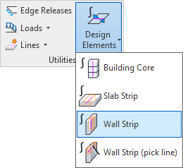
Design Elements > Wall Strip#
Wall strips are instances of a specific Revit family of category Generic Model interpreted as Design Elements by SOFiSTiK. They are a colored and oriented axis surrounded by a 3D bounding box. Placing a strip on an analytical panel and adjusting the dimension of its bounding box, allows to define:
where the Design Element should be generated in SOFiSTiK Finite Element models
which Finite Element forces to select for interpolation and integration (all Finite Elements found within the bounding box will be selected)
These integrated forces can be displayed directly in Revit using Show Results or used as input for design in the SOFiSTiK Structural Desktop (SSD).
Please refer to the Manual of module DECREATOR for more information about Design Elements, how they integrate forces and how they can be designed.

Modelling Wall Strips#
The command starts the temporary view setting SOFiSTiK Design Element Definition.
There, all model categories, apart from the Design Elements, are hidden. On the contrary, analytical elements (panels and members) are brought in the foreground.
This allows to draw easily the strip on one or several analytical elements.
If structural wall elements are selected before starting the command Wall Strip, a section box is generated around the these elements to facilitate further the strip’s modelling.
Draw a line where you want to snap the outer side of the wall strip’s bounding box
Press
ESCto finish the modelling and quit SOFiSTiK Design Element Definition temporary viewUse the shape handles to adjust the geometry of the strip’s bounding box. This adjustment is important, it defines which part of the analytical elements are selected for integration in SOFiSTiK
Automatically, the axis of the wall strip is centered, in the middle of the bounding box
(Optional) Apply again the temporary view template SOFiSTiK Design Element Definition to modify more easily the geometry of already existing strip elements
Everywhere where the wall strip is visible in Revit, a design element is placed in the corresponding SOFiSTiK system. When the system is generated, analytical elements are meshed into Finite Elements. All forces of the Finite Elements situated within the volume of the 3D bounding box are interpolated and integrated by the strip’s design element.
Important
The strip selects parts of analytical elements, the physical representation of those elements is irrelevant when modelling the strip.
Hint
In SOFiSTiK Finite Element models, members of type Beam must have their local z axis oriented opposite to the self weight’s direction. When strips of type Beam do not fulfill this criterion, a warning is issued. In this case, Revit instance property Flip Coordinate System allows to conveniently adjust the element’s orientation.
By default, the 3D bounding box is centered around the strip’s axis. Adusting the Revit instance property box alignment y allows to have the box placed in front or behind the axis.
Strip Design Elements#
Properties and Parameters#
The SOFiSTiK Structural Properties panel allows to manage properties assigned to a strip instance.
Especially the user can:
adjust the strip’s name
verify to which member type the strip is mapped to
activate/deactivate the generation of a cross section for the strip
adjust the design locations along the strip’s axis
Additionally, specific Revit shared parameters are assigned to strip.
parameter
SOFiSTiK_Categorywill show the (read-only) value Design Elementparameter
SOFiSTiK_Typewill show the (read-only) value Slab Strip or Wall Stripparameter
SOFiSTiK_DesignElement_Namedisplays the strip’s name as provided in the SOFiSTiK Structural Properties
These shared parameters can, for example, be added to schedules or used to define view filters.
Cross Sections#
When the SOFiSTiK Structural Properties Cross Section is active, a cross section is generated and mapped to the strip.
This cross section is required to conduct a design of the design element in the SOFiSTiK Structural Desktop (SSD).
By default, cross sections assigned to strips are either standard rectangular beam sections or standard rectangular column sections. Beam sections are assigned to strips which member type is Beam while column sections are assigned to strips which member type is Column. The thickness of the host analytical element and the strip’s width/magnitude define the dimensions of these cross sections.
Hint
Design Locations#
The Design Locations dialog lists positions along the element where a design should be performed (at these locations, a so-called design section from DECREATOR is created). By default, 11 locations are set, evenly distributed along the element’s length. For each location is specified, if a standard design should be conducted (check print) or if it should be handled in a specific way, e.g., by reducing the bending moment there. This specification is provided for both bending directions (y-y and z-z). More information about design section in available in the manual of DECREATOR.
Hint
Re-using an existing design location configuration is possible by coping/pasting between different design elements and/or with a previously prepared Excel table.
Results#
When available in the SOFiSTiK *.cdb, Show Results displays analysis and design results for the strips.
These results are displayed either under the beam results or under the column results, depending which member type the strip design element shows.
Hint
Displaying the Finite Element mesh in Show Results allows to check visually which Finite Elements are within the strip’s bounding box. Their forces were the ones integrated by the strip design element.