Create Objects along Curve#
 Create Objects along Curve
Command |
SOF_CABD_MAKE_PATH_WITH_GEOMETRY |
Tooltip |
Creates elements along a curve out of AutoCAD elements. |
Sidebar |
Structural Elements |
 Edit Objects along Curve
Command |
SOF_CABD_EDIT_PATH |
Tooltip |
Modifies the number of generated elements along the path. |
Sidebar |
Structural Elements |
 Update Objects along Curve
Command |
SOF_CABD_UPDATE_PATH |
Tooltip |
Distributes the source elements back to the path. |
Sidebar |
Structural Elements |
Command to create elements along a curve out of AutoCAD elements. The number of elements to be generated or a distance between the elements can be defined.
The program creates a distribution line bound to the original AutoCAD geometry. The length of the distribution line is taken from the original AutoCAD Geometry.
The elements are created along these distribution line and refer to it. The distance of the first element to the distribution line is taken into account.
The created elements can be changed independently of the source element. If the source element changes, this does not initially affect the other elements.
To reallocate the properties of the source element back to the elements along the distribution line one can use command Update Objects Along Curve.
If the geometry of the distribution line geometry changes, the distribution line and the created elements are adjusted, too.
With command Edit Objects Along Curve the number of the created elements can be changed. In this case the elements in the path are also re-adapted to the source element.
If the dialog is only opened to check the distribution rule, the elements in the path are not modified.
Available options:#
For creation of the elemente, the following options are available for use:
Fixed Number of Steps
The first element is the source element. It is not counted. The last element is generated exactly according to the lenght of the distribution line.
Step Size
The first element is the source element. Thereafter, elements are created at the given distance to the length of the distribution line. If the distribution length is not exactly divisible with the given distance, a residual length remains.
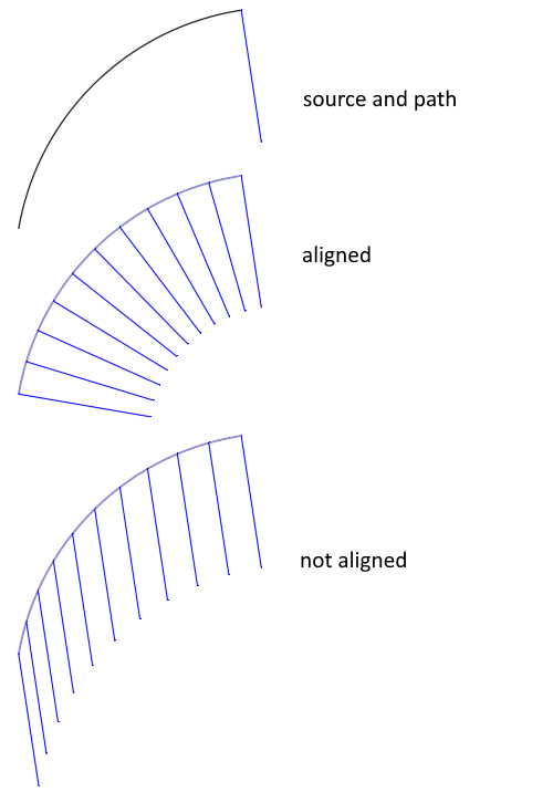
Align items to Path
Specifies whether to align each item to be tangent to the path direction. Alignment is relative to the first item’s orientation.
Example: Space Frame System#
Some structural lines are drawn to define the first frame
In this case three AutoCAD lines mark the position of the distribution lines
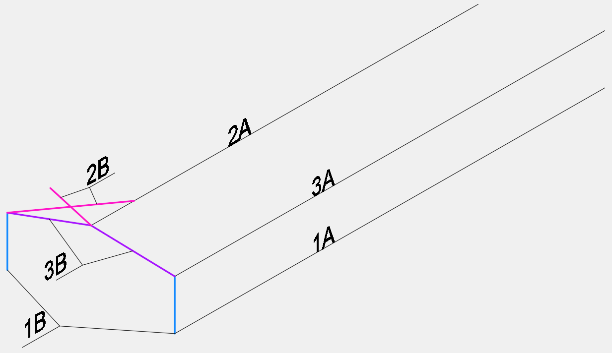
Choose command
Create Objects along CurvePick the first AutoCAD line at the base of the frame (see 1A)
Modify the distance between the generated elements in the dialog (here 3.15 meter)
Pick both colums (see 1B)
Repeat this with the bracing elements (see 2A and 2B)
Change the distance between the generated elements in the dialog (here 1.575 meter) and repeat the command with the rafter (see 3A and 3B)
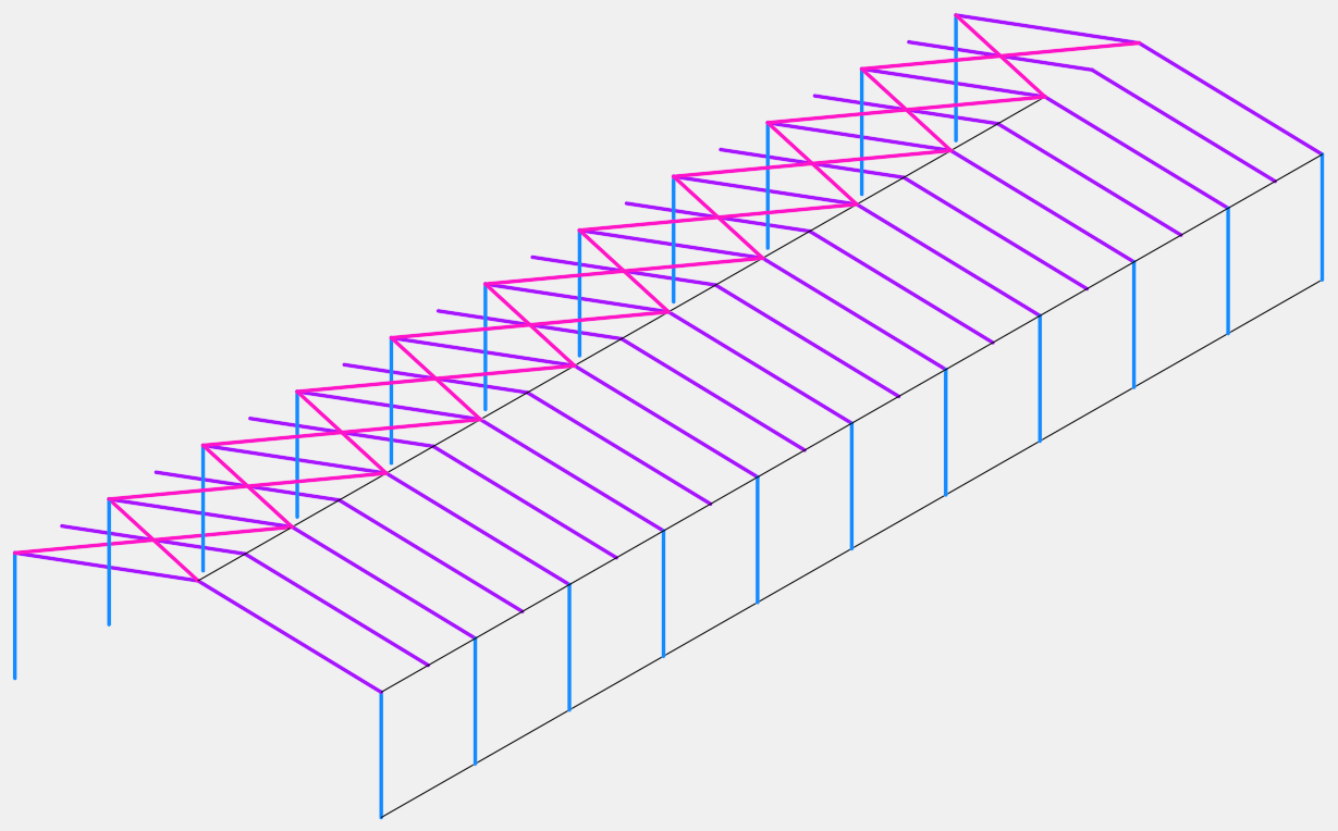
Finaly the purlin is defined
Allowed elements:#
Supported elements are structural points, structural lines, structural areas, springs and constraints between structural points and drawn tendon elements in shell systems.