Storey Elevation#
Command |
SOF_STOREY_LEVEL_EDIT |
Tooltip |
Defines storey elevations for a multi-storey building. |
Sidebar |
Structural Elements |
Storey elevations define storeys which can be used for the analysis of multi-storey buildings in the earthquake workflow. In case of a multi-tower building workflow storey elevations need to be assigned to a tower.
The definition of storeys requires the gravity direction to be aligned with the global Z-coordinate axis (positive or negative). The axis for the definition of storeys has its origin at the global coordinate system origin and always points upwards (opposed to gravity).
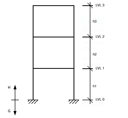
Explanation of the values:
G = Direction Dead Load
H = Direction of Storey Elevation
h1 to h3 = Inter-storey Height
LVL 0 to LVL 3 = Storey Elevation Planes
In the DWG, the storey level line is inserted in the origin point of the drawing. The storey elevation planes are shown as small areas. Each level is described by a z-value and an associated name.
For background information to the storey and tower concept see Storeys and Towers Concept. A detailed description of the properties can be found in the chapter ‘SLVL – Storey levels’ of the manual SOFiMSHC.
Visualization within the filter#
The storey levels are also available in the user defined filter.
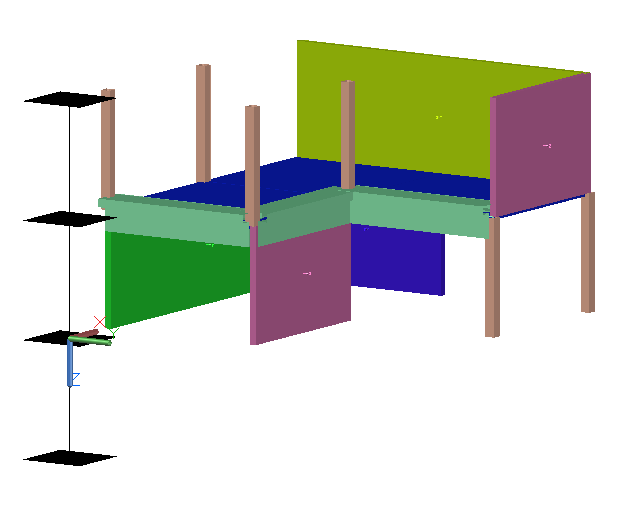
If a storey level is filtered, all elements with this z-ordinate are displayed. In addition, all elements between this level and the level below (to check the supports) and all rising components (to check the load to be applied).
Note
For the analysis programs a storey contains all the elements between the storey level and the level below, not the upwards elements shown in the filter.
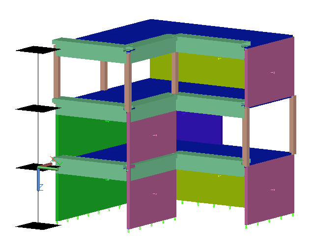
The whole system:
Level selected in the filter:
Export to the database#
Centre of rigidity and centre of mass can be calculated during the Export. This option is set by default.
If the system has kinematic instabilities some loadcases are created. These loadcases can be used to check ths system within the system viewer.
Note
To work with storey levels in the analysis programs it is necessary that the cross sections have been calculated once before the export.