Modeling Hints
The SOFiSTiK Rhinoceros Interface allows to generate a mesh from any type of curve or surface with any kind of curved geometry. Especially in case of complex shapes the geometry might contain inaccuracies or other irregularities resulting in poor mesh quality or even failure of FE meshing. Rhino however provides a lot of tools to analyse and correct irregular geometry which can be applied to solve possible problems.
Geometry Entities and Structural Elements
In general, using the SOFiSTiK Rhinoceros Interface any point, curve, surface or mesh object can be treated as structural member and passed to SOFiSTiK for meshing and further analysis. Other geometry types like polysurfaces or solids can also be treated with the Rhino Interface but will be decomposed into one of the above types during export automatically.
For solids, only the surface of the objects is meshed with shell elements when exporting the structure to SOFiSTiK. Meshing solids with volume elements is not provided directly from within the Rhino Interface. If required, this can be done using a subsequent SOFiMSHC text task within SSD or Teddy. For further information, see the manual for SOFiMSHC, command SOFIMSHC:SVO or the manual for SOFiMSHA, command SOFIMSHA:UMSH. The commands allow to create a tetrahedral mesh from a closed hull of bounding surfaces defined in Rhino.
Model Units and Sizing
A CAD system and CAD model in itself alone does not necessarily have to define or consider any model units, as long as the user knows and respects his interpretation of 1 unit of model length.
This changes as soon as you export your model to other CAD formats (e.g. step files), you choose to use your model in automated production like 3d printing or you choose to perform structural analysis on your CAD model.
Therefore, by using this extension your model becomes unit sensitive, since your FEA material models, cross sections and FEA tolerances have to match your model units in Rhino.
In case you have not given any consideration to modelling units when creating a new Rhino file, you may always check and possibly fix your model units with the Rhino command _Units.
Mismatching modelling units (e.g. Rhino units of millimeter but model sizes representing meters in your intended SOFiSTiK FEA workflow) may result in meshing problems due to tolerances.
Explode Polysurfaces and Solids
By default, polysurfaces or solids are automatically decomposed into separate surfaces during export.
In this case however, a possible one to one correspondence between structural surface numbers in Rhino and the surface numbers in the SOFiSTiK database is lost,
which might impede later referencing of the surfaces by their numbers for application of loads etc.
So, if the surface numbers are required in any subsequent analysis step within SOFiSTiK, polysurfaces and solids should be exploded into
their composing surfaces prior to the export using the Rhino command _Explode.
Same holds for closed or periodic surfaces. For meshing reasons, closed, periodic surfaces, like surfaces of revolution or spherical surfaces
will be split into two halfs during export automatically. To avoid numbering problems in subsequent analysis steps, closed surfaces should
also be split manually e.g. by using the Rhino command _Split Isocurve.
Avoid Polysurfaces
As described in the previous section, polysurfaces can be handled with the SOFiSTiK Rhino Interface. However, we recommend to split polysurfaces into its composing surfaces for the reasons described before or to avoid to generate polysurfaces at all.
Polysurfaces might be explicitly created by the user. However, under certain conditions,
polysurfaces might also be the unexpected result of
modeling techniques applied. This holds in particular for geometric operations like sweeping
(_sweep1 or _sweep2) or surfaces created by a set of bounding edges (_EdgeSrf).
There a various Rhino surface commands which are sensitive to geometric properties like continuity of edges as
basis for surface creation, and thus, will result in polysurfaces to keep continuity conditions.
The example below illustrates this effect. This behavior might be unexpected
for the user, especially if continuity constraints of bounding edges, e.g. kinks are not directly visible.
Yet, the continuity of the bounding edges will affect the surface and result in the generation of polysurfaces.
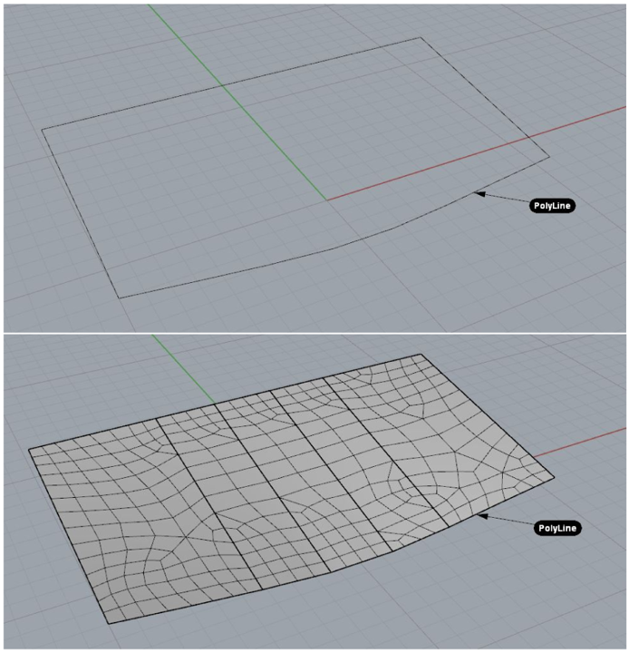
If the kinks are not necessary or intended by the user, the generation of polysurfaces might be undesirable with respect to the assignment of SOFiSTiK structural properties but also for other geometric operation on Rhino.
There are workarounds like using preferably surface commands less sensitive to such continuity
constraints (e.g. _Patch or _Loft).
Those geometric operations already offer options to avoid polysurface generation. Another remedy is
to rebuild the bounding edges before using
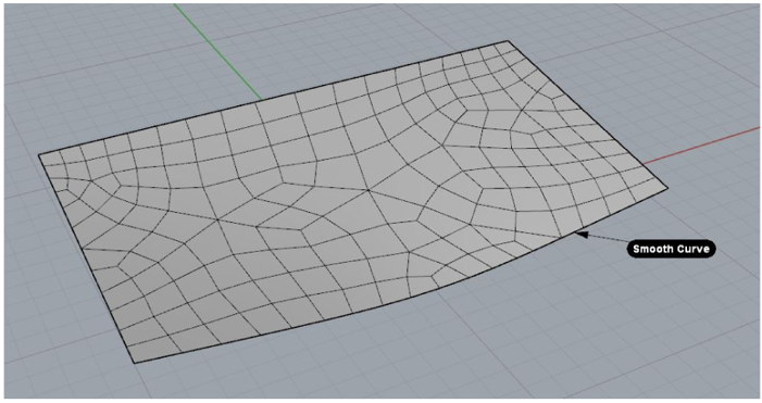
them in such critical Rhino commands. For example, the Rhino command ‘_CurveThroughPolyLine’ will
convert a polyline into a smooth curve.
See “Smooth surface after conversion of polyline” in Figure bellow:
Extrusions in Rhino 7 and Latest Versions of Rhino 6
Rhino introduced new modelling functionalities in form of special extrusions, e.g. by using the Gumball. Some of the resulting geometric entities are not yet directly supported by this SOFiSTiK extension. The full support for those type of geometric entities will be provided with the next major release. Meanwhile, you may still work with theese modelling functionalities and entities. Simply use the Rhino ‘_Explode’ command to apply SOFiSTiK structural properties on them.
Merge Tiny Boundary Edges
In certain cases, the geometry of a Rhino surface may include very short boundary edges which may result in extreme local refinements on the
generated FE mesh. The boundary edges of a Rhino surface are generated automatically by Rhino and by default not visible for the user, but can
be visualized and explored using the Rhino command _showEdges
(Rhino menu: ).
Using the commands _MergeEdge or _MergeAllEdges such short edges can be merged with geometrically
coinciding edges, given that their joining angle lies below a certain threshold.
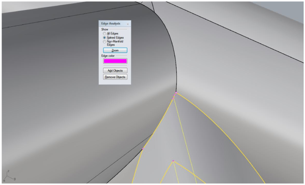
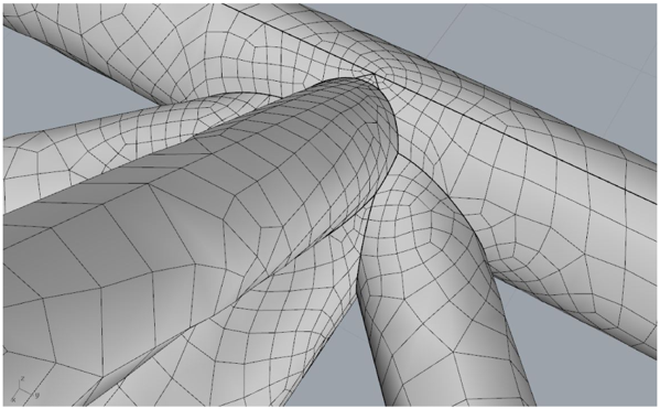
Smooth Mesh of tubular joint contains extreme local refinement for no apparent reason:
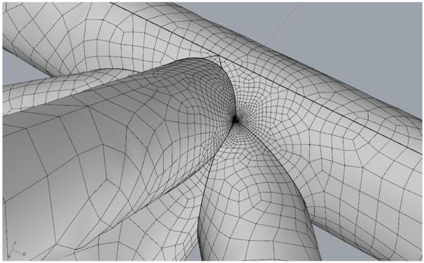
Bellow you can see that Command _showEdges shows tiny edge segments at the intersection between the tubes:
After joining the edge segments, mesh refinement is resolved:
Manual Generation of Intersection Curves
As described in the general program functionalities (see link), all geometric points, curves or surfaces exported from Rhino will be intersected and merged in order to get a consistent geometric model for FE meshing. For example, if two surfaces cross each other, SOFiMSHC will automatically generate an intersection curve serving as a constraining edge which will be matched by adjacent quad elements.
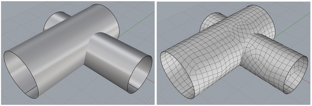
However, especially at the intersection of two curved surfaces, the automatic surface intersection algorithm within SOFiMSHC might fail or might produce inaccurate intersections with the result that the FE mesh between the two surfaces is not consistent and thus, mechanically not properly connected.
No intersection generated between curved surfaces:
In such cases, the user could disable the automatic intersection with other surfaces:
‘SOFiSTiK structural surface property dialog
→ disable automatic intersection → intersection with structural surfaces’
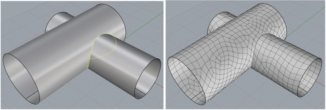
and then generate the intersection curve manually within Rhino
(by e.g. using the command _Intersect, Rhino menu: →
→ ’).
The generated curve should then be marked as ’Structural curve’ such that the curve will be passed to
FE meshing as well. As long as the option
‘intersection with structural curves’ is still active in the structural surface property set, the exported
intersection curve will be integrated
in the region geometry as constraint for a consistent mesh.
Manual generation of intersection curve:
Re-building Curves and Surfaces
In certain cases, especially when the Rhino model has been imported from other CADsystems, the geometry (or its parametrization) of a curve or a surface might be strongly distorted with the effect that meshing of the structure results also in distorted elements or is not possible at all.
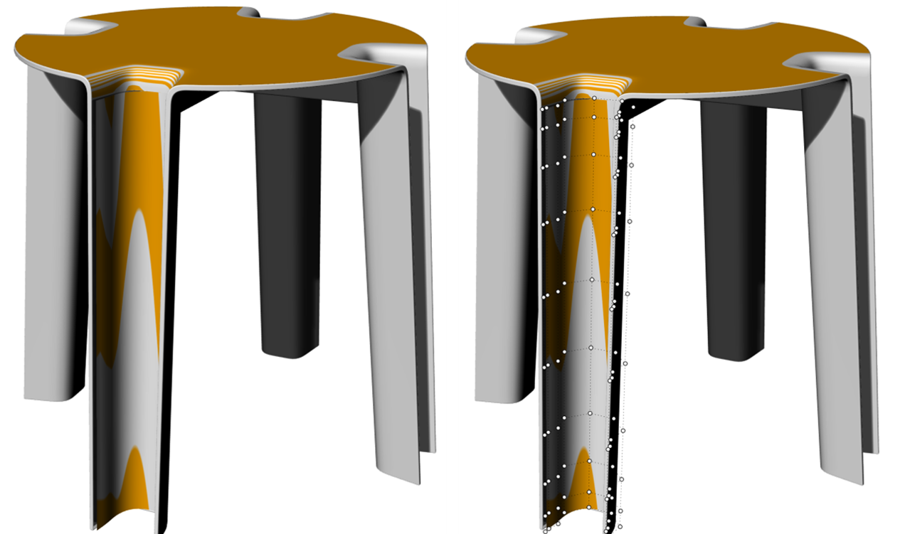
Non-optimal parameterization inspected with _Zebra and _PointsOn:
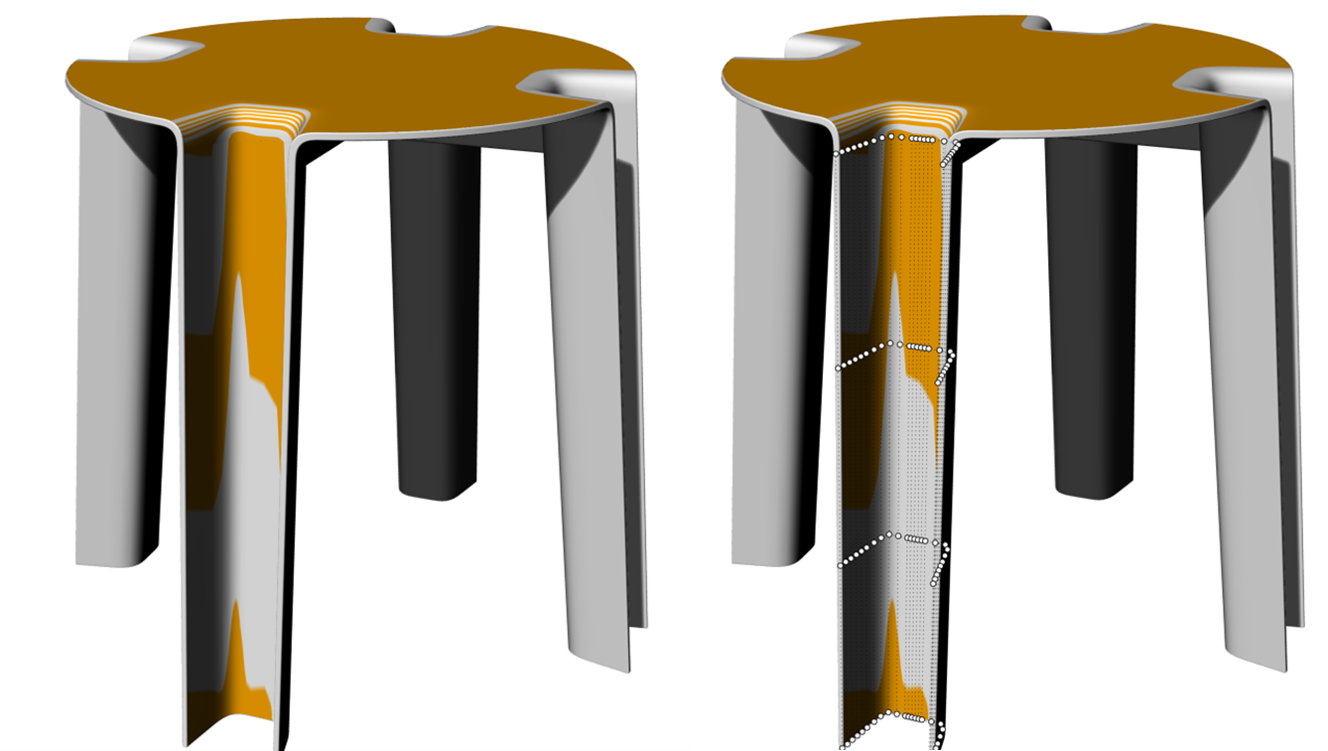
In order to resolve such an issue, the user could first activate the NURBS control points
(Rhino command _PointsOn, menu: )
to check the distribution of the points. If the points on the surface are irregularly distributed,
the user could try to simplify the geometry using the Rhino commands _FitCrv or _FitSrv.
Another remedy might be to rebuild the surface using the _ReBuild command.
Another way to detect possible distortions, small geometric defects or parameterization issues is to use Rhino
visual inspection tools (_Zebra).
Optimized parameterization due to _ReBuild:
